Spis treści
Supported displays
OLED (SSD1306)
Some boards have such display by default and should work out of the box.
For T-Beam, the preferred connection is SDA=GPIO21, SCK=GPIO22. Some displays can directly be connected 1:1 to 3v3/GND/22/21, but note that some OLED display have connections in the order GND/VDD/SCK/SDA, in which case wiring is more difficult (swap GND/VDD).
Auto-configuration should usually work
OLED (SH1106)
Works similarly to SSD1306. If same wiring is used, most likely autoconfig is set to SSD1306 and must be manually changed to SH1106.
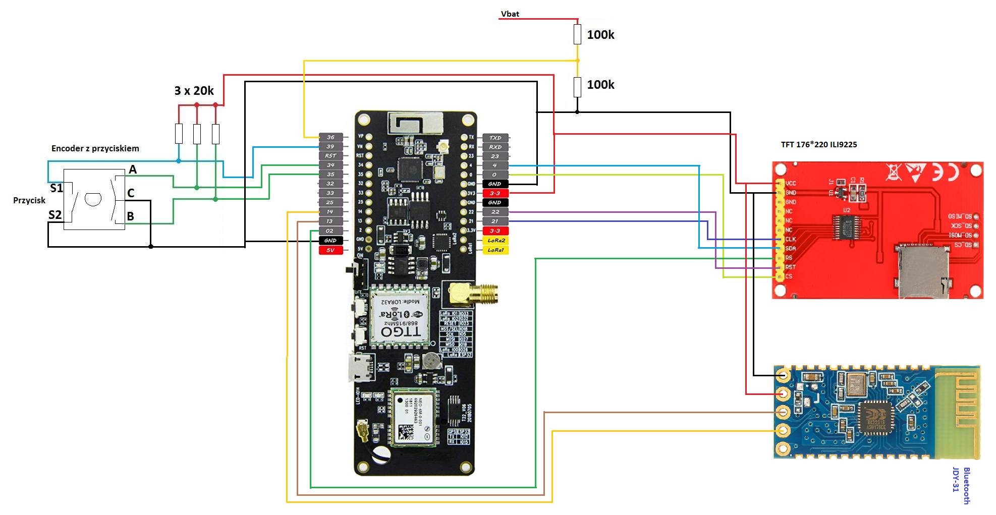
ILI 9225
Preferred connection on T-Beam 0.7 is SDA=4, CLK=21, RST=22, RS=2, CS=0 Note: This is identical to the config used by https://skp.wodzislaw.pl/wp-content/uploads/2019/03/sch_tft_tbeam.png
Preferred connection on T-Beam 1.0 and 1.1 is SDA=4, SCL=13, RST=14, RS=2, CS=0 Note: THis is DIFFERENT to the axp tgt wiring on skp.wodzislaw.pl
ILI 9341
Can be used similarily to ILI 9225. Display type must manually be configured in the settings. (Auto-detect cannot distinguish between ILI9225 and ILI9341, and will configure type ILI9225. You have to change that to ILI9341).
Recommended wiring is identical to ILI9225. With labels on my test display, for T-Beam 1.0/1.1: CS=0, RESET=14, DC=2, SDI(MOSI)=4, SCK=13, SDO(MISO) is not connected
Some displays do not have a CS pin. These should work fine (only connect the other pins).
You may have to decrease SPI speed. The default 40 MHz might be too high. The data sheet of ILI9341 states a clock cycle of 100ns, i.e. a maximum clock frequency of 10 MHz. In practice, using 20 MHz usually is no problem. (The ILI9225 display specs allow 20ns clock cycle, i.e. 50 MHz max, so the default 40 MHz is fine for ILI9225 - but not for ILI9341).
VDD and LED is wired to 3.3V; for boards supporting 5V and 3.3V operation, the jumper for disabling the voltage regulator on the display needs to be set.