25 KiB
stlink Tools Tutorial
Available tools and options
| Option | Tool | Description | Available since |
|---|---|---|---|
| --flash=n[k, M] | st-flash | One can specify --flash=128k for example, to override the default value of 64k for the STM32F103C8T6 to assume 128k of flash being present. This option accepts decimal (128k), octal 0200k, or hex 0x80k values.Leaving the multiplier out is equally valid, e.g.: --flash=0x20000. The size may be followed by an optional "k" or "M" to multiply the given value by 1k (1024) or 1M (1024 x 1024) respectively.One can read arbitary addresses of memory out to a binary file with: st-flash read out.bin 0x8000000 4096. In this example 4096 bytes are read and subsequently written to out.bin.Binary files (here: in.bin) are written into flash memory with: st-flash write in.bin 0x8000000 |
v1.4.0 |
| --format | st-flash | Specify file image format to read or write. Valid formats are binary and ihex. |
v1.3.0 |
| --freq=n[k, M] | st-info st-flash st-util |
The frequency of the SWD/JTAG interface can be specified, to override the default 1800 kHz configuration. This option solely accepts decimal values with the unit Hz being left out. Valid frequencies are:5k, 15k, 25k, 50k, 100k, 125k, 240k, 480k, 950k, 1200k (1.2M), 1800k (1.8M), 4000k (4M). |
v1.6.1 |
| --opt | st-flash | Optimisation can be enabled in order to skip flashing empty (0x00 or 0xff) bytes at the end of binary file. This may cause some garbage data left after a flash operation. This option was enabled by default in earlier releases. |
v1.6.1 |
| --reset | st-flash | Trigger a reset after flashing. The default uses the hardware reset through NRST pin.A software reset (via AIRCR; since v1.5.1) is used, if the hardware reset failed (NRST pin not connected). |
v1.0.0 |
| --connect-under-reset | st-info st-flash st-util |
Connect under reset. Option makes it possible to connect to the device before code execution. This is useful when the target contains code that lets the device go to sleep, disables debug pins or other special code. | v1.6.1 |
| --hot-plug | st-info st-flash st-util |
Connect to the target without reset. | v1.6.2 |
| --probe | st-info | Display hardware information about the connected programmer and target MCU. | v1.2.0 |
| --version | st-info st-flash st-util |
Print version information. | v1.3.0 |
| --help | st-flash st-util |
Print list of available commands. |
Reading & Writing Option Bytes
Example to read and write option bytes:
./st-flash --debug read option_bytes_dump.bin 0x1FFF7800 4
./st-flash --debug write option_bytes_dump.bin 0x1FFF7800
st-flash: Checksum for binary files
When flashing a file, a checksum is calculated for the binary file, both in md5 and the sum algorithm.
The latter is also used by the official ST-LINK utility tool from STMicroelectronics as described in the document: UM0892 - User manual STM32 ST-LINK utility software description.
stlink-gui
The stlink toolset also provides a GUI which is an optional feature. It is only installed if a gtk3 toolset has been detected during package installation or compilation from source. It is not available for Windows. If you prefer to have an user interface on the latter system, please use the official ST-LINK Utility instead.
The stlink-gui offers the following features:
- Connect/disconnect to a present STlink programmer
- Display basic device information
- Select a binary file from the local filesystem to flash it to the detected device connected to the programmer
- Export the memory of the connected chip to a file which can be saved to the local filesystem
- Display of the memory address map in the main window for each, the device memory and a loaded binary file
Within the GUI main window tooltips explain the available user elements.
HowTos & solutions to common problems
a) Verify if udev rules are set correctly (by Dave Hylands)
To investigate, start by plugging your STLINK device into the usb port. Then run lsusb. You should see an entry something like the following:
Bus 005 Device 017: ID 0483:374b STMicroelectronics ST-LINK/V2.1 (Nucleo-F103RB)
Note the bus number (005) and the Device (017). You should then do:
ls -l /dev/bus/usb/005/017 (replacing 005 and 017 appropriately).
On my system I see the following:
crw-rw-rw- 1 root root 189, 528 Jan 24 17:52 /dev/bus/usb/005/017
which is world writable (this is from the MODE:="0666" below). I have several files in my /lib/udev/rules.d directory. In this particular case, the 49-stlinkv2-1.rules file contains the following:
# STM32 nucleo boards, with onboard STLINK/V2-1
# ie, STM32F0, STM32F4.
# STM32VL has STLINK/V1, which is quite different

SUBSYSTEMS=="usb", ATTRS{idVendor}=="0483", ATTRS{idProduct}=="374b", \
    MODE:="0666", \
    SYMLINK+="stlinkv2-1_%n"

# If you share your linux system with other users, or just don't like the
# idea of write permission for everybody, you can replace MODE:="0666" with
# OWNER:="yourusername" to create the device owned by you, or with
# GROUP:="somegroupname" and mange access using standard unix groups.
and the idVendor of 0483 and idProduct of 374b matches the vendor id from the lsusb output.
Make sure that you have all 3 files from /config/udev/rules.d in your /lib/udev/rules.d directory. After copying new files or editing existing files in /lib/udev/rules.d you should run the following:
sudo udevadm control --reload-rules
sudo udevadm trigger
to ensure that the rules actually take effect. Using the trigger command means that you shouldn't need to unplug and replug the device, but you might want to try that for good measure as well.
If the VID:PID of your device doesn't match those in any of the 3 files, then you may need to create a custom rule file to match your VID:PID.
b) NOTE: Chinese Fake-Chips CKS32F103C8T6 or CS32F103C8T6 being marked as "STM32F103C8T6"
In contrast to "Clone chips" which identify themselves as such by their official marking (manufacturer, model, etc.), so called "Fake chips" do not. Instead counterfeiters try to copy the outer appearance of the original and thus are very hard to detect. Possible malfunction then may lead to various effects and issues during operation also in in connection with this toolset.
As of December 2019 several so called "Bluepill-Boards" with a STM32F103C8T6 appeared on the market that do not hold the original part.
In this known example one finds the counterfeited "STM32F103C8T6" MCUs to identify themselves with chip-id 0x2ba01477 instead of 0x1ba01477.
In the following you find some hints on how to identify your chip and track down fraud:
- How to Detect STM32 Fakes
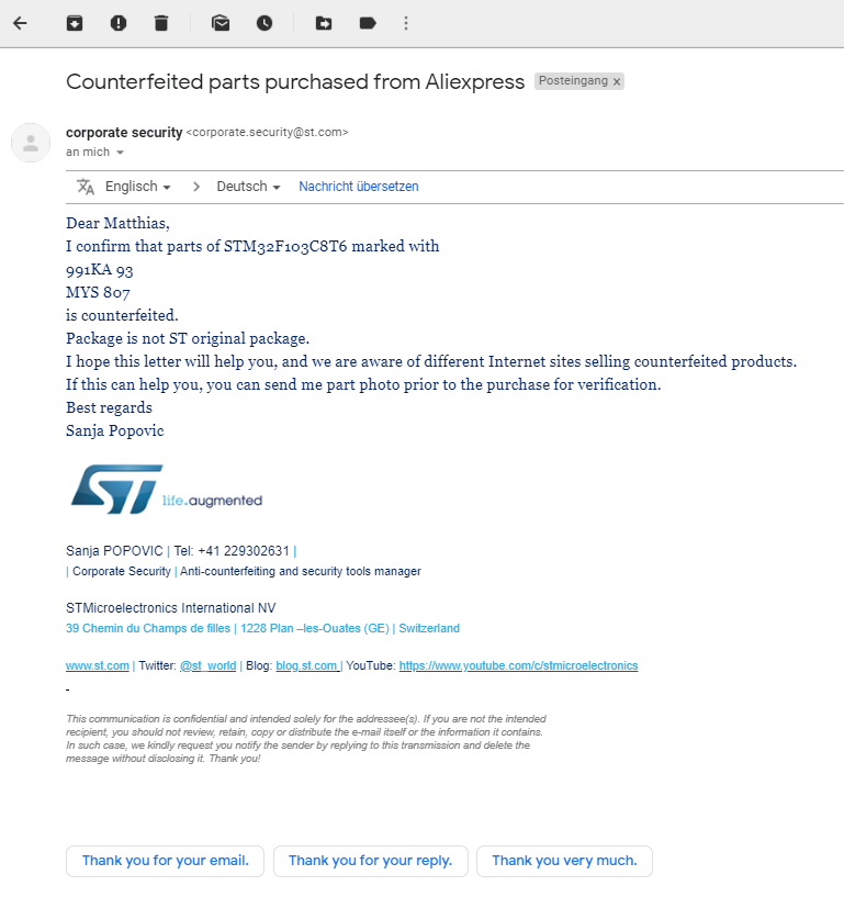
- Confirmation by STMicroelectronics (Marking: 991KA 93 MYS 807)
- STM32 Clones: The Good, The Bad And The Ugly
However it appears that not all counterfeited parts cause problems during operation, but some are known to not even being able to execute a basic "blinky" example binary. Further there can be problems that may not even show up or affect you directly, but somewhen later in time (or maybe never). This demonstrates there is no guarantee for a proper working chip with equal functionality compared to the original.
Please keep this in mind and be sceptical when facing problems with this type of boards.
Check your hardware and try to identify what you have in front of you before assuming a bug in the stlink toolset.
Please let us know, if you come across any further websites or tutorials that help to identify STM32 fake chips so we can list them here to help others.
c) Appearance of the warning message WARN src/common.c: unknown chip id!
The chip ID is the main identifier for STM32 MCU and their specific type and provides primary information on flash and SRAM architecture.
This so called DBGMCU_IDCODE register is allocated either at memory address 0xE0042000 or 0x40015800.
A failure of chip identification results in the error WARN src/common.c: unknown chip id!.
There are different variants of this message that refer to different issues:
unknown chip id! 0--> Target chip (board) is unknown.- Microcontroller is in stop/standby mode.
- The signals
DIOandCLKare reversed on the SWD-Interface.
unknown chip id! 0x3748--> A target chip (board) cannot be detected.- No target is connected --> In this case
st-info --probedisplayschip id 0x0748with STLINK/V2 andchip id 0x03e8with STLINK-V3. - The chip is connected but has gone into an undefined state of operation where the SWD pins are unresponsive. --> Try to use
--connect-under-resetwhile pressing the reset button on the target board. - A firmware-issue prevents the programmer from normal operation. --> Ensure that your programmer runs the latest firmware version and consider to upgrade any older version by using the official firmware upgrade tool provided by STMicroelectronics.
- No target is connected --> In this case
unknown chip id! 0xe0042000--> The memory register holding the information on the chip ID could not be read. The following problems may lead to this case:- This problem is caused by the SWDIO and SWCLK being configured for other purpose (GPIO, etc) other than Serial Wire configuration or Jtag --> A possible solution to this is to short the
BOOT0pin withVDD(1) and to reset the chip / board by the execuingst-flash erasein order to return the MCU back to normal operation. AfterwardsBOOT0should be set back toGND(0). - There is a hardware defect in the connection between the MCU and the used programmer (solder points, cables, connectors).
- This problem is caused by the SWDIO and SWCLK being configured for other purpose (GPIO, etc) other than Serial Wire configuration or Jtag --> A possible solution to this is to short the
d) Understanding hardware and software reset functionality for st-flash and reset-related device recovery
Typically a reset signal is sent via the reset pin NRST. Using st-flash for flashing results in the following behaviour:
- without the
--resetoption:st-flash writeresults in one reset signal on theNRSTline - with the
--resetoption:st-flash write --resetresults in two subsequent reset signals on theNRSTline
Depending on the used programmer the hardware reset line is not always connected.
This is especially the case for low-cost STLINK/V2 clone programmers.
Here the SWD connector consists of only 4 pins: VCC, SWCLK, GND and SWDATA.
When the physical reset line NRST is not connected, a reset is initiated by software via SWD_SWDIO/JTAG_TMS (software reset).
Just as mentioned above, flashing is possible here eiher with and without the --reset option.
Configuring the STM32 pin JTAG_TMS/SWD_SWDIO as an output now also prevents the SWD interface from flashing and resetting the device.
In consequence this constellation typically requires a hard reset to allow for the ST-Link/V2 programmer to reconnect to the target at all.
As soon as the device is in DFU mode, the JTAG_TMS/SWD_SWDIO pin is left in the default state with all JTAG pins available.
Here flashing of the device is now possible with and without the --reset option.
The debug command (gdb) monitor jtag_reset sends a hard reset signal via the NRST pin to reset the device and allows for flashing it (again).
e) Note on setting hardware breakpoints for external bus (Example: STM32H735-DK)
GDB is setting breakpoints based on the XML memory map designation of rom or ram, which is hardcoded in st-util for a given processor.
However the external bus can be RAM or ROM depending on design.
The STM32H735-DK has external FLASH at address 0x90000000. As a result, because the entire external memory range is ram as it could be either,
software breakpoints (Z0) get sent when a breakpoint is created and they never get tripped as the memory area is read only.
f) UART-Access via a virtual COM port
Access to the Universal Asynchronous Receiver Transmitter (UART) via a virtual COM port is not related to the stlink toolset itself. It is an independent feature that should natively be available on UNIX-based operating systems. Windows operating systems require the installation of a virtual COM device driver. The appropriate device driver is downloaded and installed automatically via Windows Update in the background as soon as the device is plugged-in for the first time. A connected ST-LINK programmer with UART functionality is detected as a CDC (ACM) USB device. After each reset the device will be reloaded and will pop up as /dev/ttyACM0 or /dev/ttyACM1 depending on the specific design.
UART connections to the interface are typically initiated with a serial terminal. For UNIX operating systems we recommend to use either minicom (terminal-based) or cutecom (GUI-based). Windows users should have a look at Teraterm.
Most common and established settings for the interface are 115200 or 9600 baud together with the 8-N-1 configuration, standing for (8) data bits, no parity bit (N) and (1) stop bit. Please refer to relevant literature on the UART interface for more detailed technical information and limitations.
Note: On some debian-based UNIX-based systems the modemmanager package is installed by default. In has been reported that this tool unfortunately may delay the release of the serial port to applications which is handled by the operating system in the background. Subseqently the CDC/ACM device is also delayed after each reset. This typically includes not only the connection itself, but also some programming operations (at least those using the mass storage emulation). However one can not predict the behaviour exactly - in some cases the boards may be essentially useless or even working fairly well.
Proper determined functionality can be achieved by uninstalling the modemmanager package or by setting an appropriate udev device rule.
( Content below is currently unrevised and may be outdated as of Mar 2021. )
Using the GDB server
This assumes you have got the libopencm3 project downloaded in ocm3.
The libopencm3 project provides a firmware library, with solid examples for Cortex M3, M4 and M0 processors
from any vendor. It has some good, reliable examples for each of the Discovery boards.
Even if you don’t plan on using libopencm3, the examples they provide will help you verify that:
- Your installed toolchain is capable of compiling for cortex M3/M4 targets
- stlink is functional
- Your arm-none-eabi-gdb is functional
- Your board is functional
A GDB server must be started to interact with the STM32 by running st-util tool :
$> st-util

# Full help for other options (listen port, version)
$> st-util --help
Then, GDB can be used to interact with the kit:
$> $TOOLCHAIN_PATH/bin/arm-none-eabi-gdb example_file.elf
From GDB, connect to the server using:
(gdb) target extended localhost:4242
GDB has memory maps for as many chips as it knows about, and will load your project into either flash or SRAM based on how the project was linked. Linking projects to boot from SRAM is beyond the scope of this document.
Because of these built in memory maps, after specifying the .elf at the command line, now we can simply “load” the target:
(gdb) load
st-util will load all sections into their appropriate addresses, and “correctly” set the PC register. So, to run your freshly loaded program, simply “continue”
(gdb) continue
Your program should now be running, and, if you used one of the blinking examples from libopencm3, the LEDs on the board should be blinking for you.
Using the gdb server
To run the gdb server:
$ make && [sudo] ./st-util

There are a few options:

./st-util - usage:

  -h, --help		Print this help
  -vXX, --verbose=XX	Specify a specific verbosity level (0..99)
  -v, --verbose		Specify generally verbose logging
  -p 4242, --listen_port=1234
			Set the gdb server listen port. (default port: 4242)
  -m, --multi
			Set gdb server to extended mode.
			st-util will continue listening for connections after disconnect.
  -n, --no-reset, --hot-plug
			Do not reset board on connection.
The STLink device to use can be specified using the --serial parameter.
Then, in your project directory, someting like this... (remember, you need to run an ARM gdb, not an x86 gdb)
$ arm-none-eabi-gdb fancyblink.elf
...
(gdb) tar extended-remote :4242
...
(gdb) load
Loading section .text, size 0x458 lma 0x8000000
Loading section .data, size 0x8 lma 0x8000458
Start address 0x80001c1, load size 1120
Transfer rate: 1 KB/sec, 560 bytes/write.
(gdb)
...
(gdb) continue
Resetting the chip from GDB
You may reset the chip using GDB if you want. You'll need to use `target extended-remote' command like in this session:
(gdb) target extended-remote localhost:4242
Remote debugging using localhost:4242
0x080007a8 in _startup ()
(gdb) kill
Kill the program being debugged? (y or n) y
(gdb) run
Starting program: /home/whitequark/ST/apps/bally/firmware.elf
Note that st-link does not support 'run', as it does not load arbitrary programs without explicit commands. In order to continue, one can use 'monitor reset' to reset the MCU.
Remember that you can shorten the commands. tar ext :4242 is good enough
for GDB.
If you need to send a reset signal, you can use the following command:
(gdb) monitor jtag_reset
Disassembling THUMB code in GDB
By default, the disassemble command in GDB operates in ARM mode. The programs running on CORTEX-M3 are compiled in THUMB mode. To correctly disassemble them under GDB, uses an odd address. For instance, if you want to disassemble the code at 0x20000000, use:
(gdb) disassemble 0x20000001
Running programs from SRAM
You can run your firmware directly from SRAM if you want to. Just link it at 0x20000000 and do
(gdb) load firmware.elf
It will be loaded, and pc will be adjusted to point to start of the code, if it is linked correctly (i.e. ELF has correct entry point).
Writing to flash
The GDB stub ships with a correct memory map, including the flash area.
If you would link your executable to 0x08000000 and then do
(gdb) load firmware.elf
then it would be written to the memory.