11 KiB
SSB modulator plugin
Introduction
This plugin can be used to generate a single sideband or double sidebands modulated signal.
Interface
The top and bottom bars of the channel window are described here
☞ In order to toggle USB or LSB mode in SSB mode you have to set the "BW" in channel filter cutoff control (8) to a positive (USB) or negative (LSB) value. The above screenshot shows a USB setup. See the (7) to (9) paragraphs below for details.
☞ The channel marker in the main spectrum display shows the actual band received taking in channel filtering into account.
1: Frequency shift from center frequency of transmission
Use the wheels to adjust the frequency shift in Hz from the center frequency of transmission. Left click on a digit sets the cursor position at this digit. Right click on a digit sets all digits on the right to zero. This effectively floors value at the digit position. Wheels are moved with the mousewheel while pointing at the wheel or by selecting the wheel with the left mouse click and using the keyboard arrows. Pressing shift simultaneously moves digit by 5 and pressing control moves it by 2.
2: Channel power
Average total power in dB relative to a +/- 1.0 amplitude signal generated in the pass band.
3: Binaural mode
Use this button to toggle between monaural and binaural mode. Monaural is classical single sideband or double sidebands modulation. In binaural mode I and Q samples are taken from the left and right stereo channels (or reversed).
When in monaural mode the icon shows a single loudspeaker and when in binaural mode it shows a pair of loudspeakers.
4: Reverse left and right channels in binaural mode
Effective only in binaural mode: reverses left and right audio channels so that the left is connected to Q and the right to the I complex signal channel.
5: Sideband flip
Flip LSB/USB. Mirror filter bandwidth around zero frequency and change from LSB to USB or vice versa. Works in SSB mode only.
6: SSB/DSB
Selects between SSB and DSB operation. When in SSB mode the icon shows a single sideband spectrum (USB side). When in DSB mode the icon shows a double sideband spectrum. In SSB mode the shape of the icon represents LSB or USB operation.
7: Spectrum display frequency span
The transmitted signal in the sideband (SSB) or sidebands (DSB) sample rate of 48 kHz is further decimated by a power of two before being applied to the channel spectrum display and used to set the in channel filter limits. This effectively sets the total available bandwidth depending on the decimation:
- 1 (no decimation): 24 kHz (SSB) or 48 kHz (DSB)
- 2: 12 kHz (SSB) or 24 kHz (DSB)
- 4: 6 kHz (SSB) or 12 kHz (DSB)
- 8: 3 kHz (SSB) or 6 kHz (DSB)
- 16: 1.5 kHz (SSB) or 3 kHz (DSB)
The span value display is set as follows depending on the SSB or DSB mode:
- In SSB mode: the span goes from zero to the upper (USB: positive frequencies) or lower (LSB: negative frequencies) limit and the absolute value of the limit is displayed.
- In DSB mode: the span goes from the lower to the upper limit of same absolute value and ± the absolute value of the limit is displayed.
This is how the Span (7) and bandpass (8, 9) filter controls look like in the 3 possible modes:
DSB:
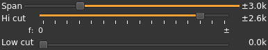
- Decimation factor is 4 hence span is 6 kHz from -3 to +3 kHz and ±3.0k is displayed
- In channel filter bandwidth is 5.2 kHz from -2.6 to +2.6 kHz and ±2.4k is displayed
- In channel filter "low cut" is disabled and set to 0
USB:
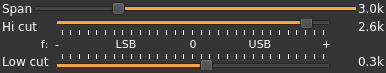
- Decimation factor is 4 hence span is 3 kHz from 0 to 3 kHz and 3.0k is displayed
- In channel filter upper cutoff is 2.4 kHz and 2.6k is displayed
- In channel filter lower cutoff is 0.3 kHz and 0.3k is displayed
- Hence in channel filter bandwidth is 2.3 kHz
LSB:

- Decimation factor is 4 hence span is 3 kHz from 0 to -3 kHz and -3.0k is displayed
- In channel filter lower cutoff is -2.6 kHz and -2.6k is displayed
- In channel filter upper cutoff is -0.3 kHz and -0.3k is displayed
- Hence in channel filter bandwidth is 2.3 kHz
8: "BW": In channel bandpass filter cutoff frequency farthest from zero
Values are expressed in kHz and step is 100 Hz.
- In SSB mode this is the upper (USB: positive frequencies) or lower (LSB: negative frequencies) cutoff of the in channel single side band bandpass filter. The value triggers LSB mode when negative and USB when positive
- In DSB mode this is half the bandwidth of the double side band in channel bandpass filter therefore the value is prefixed with the ± sign.
9: "Low cut": In channel bandpass filter cutoff frequency closest to zero
Values are expressed in kHz and step is 100 Hz.
- In SSB mode this is the lower cutoff (USB: positive frequencies) or higher cutoff (LSB: negative frequencies) of the in channel single side band bandpass filter.
- In DSB mode it is inactive and set to zero (double side band filter).
10: Volume
This is the volume of the audio signal from 0.0 (mute) to 2.0 (maximum). It can be varied continuously in 0.1 steps using the dial button. The Loudspeaker button is the audio mute toggle.
11: Level meter in %
- top bar (beige): average value
- bottom bar (brown): instantaneous peak value
- tip vertical bar (bright red): peak hold value
You should aim at keeping the peak value below 100% using the volume control
12: Audio compression
Use this button to toggle audio compression on or off.
13: Input source control
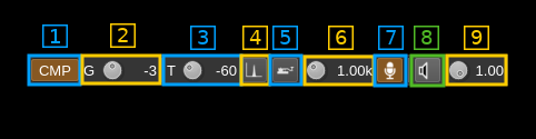
13.1: Audio compressor
Activate/deactivate it for file and audio input only.
13.2: Audio compressor input gain
Gain in dB before compression
13.3: Audio compressor threshold
Threshold in dB above which compression applies a.k.a. "knee" point. The lower the value the harder is the compression and consequently higher the distortion.
13.4: Tone input select
Switches to the tone input. You must switch it off to make other inputs available.
13.5: Morse keyer input select
Switches to the Morse keyer input. You must switch it off to make other inputs available.
13.6: Tone frequency (kHz)
Adjusts the tone frequency from 0.1 to 2.5 kHz in 0.01 kHz steps
13.7: Audio input select and select audio input device
Left click to switch to the audio input. You must switch it off to make other inputs available.
Right click to select audio input device. See audio management documentation for details.
13.8: Audio feedback
Left click to activate audio feedback.
Right click to select audio output device for audio feedback. See audio management documentation for details.
14: CW (Morse) text
Enter the text to be keyed when Morse input is active and in text mode
15: Clear CW text
Clears the CW (Morse) text
16a: Morse keyer controls (line1)

16a.1: CW keying speed
Sets the CW speed in Words Per Minute (WPM). This is based on the word "PARIS" sent 5 times. For 5 WPM the dot length is 240 ms. In other terms the dot length is calculated as 1.2 / WPM seconds. The dot length is used as the base to compute other timings:
- Element (dot or dash) silence separator: 1 dot length
- Dash: 3 dot lengths
- Character silence separator: 3 dot lengths
- Word silence separator: 7 dot lengths
16a.2: Dots keying
Switch this button to send dots continuously
16a.3: Dashes keying
Switch this button to send dashes continuously
16a.4: Text keying
Switch this button to send the text typed into the text box (13)
16a.5: Text auto repeat
Switch this button to auto repeat the text keying
16a.6: Text play/stop
Use this button to stop sending text. When resuming keying restarts at the start of text
16b: Morse keyer controls (line2)

⚠ WARNING: what follows is not really useful if you do not use a proper Morse keyer with direct audio feedback. There is a significant audio delay either with the direct monitoring or by monitoring the transmitted signal so keying with this audio as feedback is not practical
16b.1: Activate morse keys keyboard and mouse control
This disables text or continuous dots or dashes. Toggle input from keyboard or mouse (see 16b.3). Occasionally the focus may get lost and you will have to deactivate and reactivate it to recover the key bindings.
16b.2: Iambic or straight
Choose iambic or straight keying style. When straight is selected the dot or dash key may be used.
16b.3: Mouse control pad
When keyboard and mouse control is activated move the pointer to this area to use the left button as the dot paddle and the right button as the dash paddle. In straight mode both buttons have the same effect (key down).
16b.4: Register dot key
Click on the button and while selected type a character or character and modifier (Shift + key for example) to select which key is used for dots. The key or key sequence appears next (here dot .)
16b.5: Register dash key
Click on the button and while selected type a character or character and modifier (Shift + key for example) to select which key is used for dashes. The key or key sequence appears next (here dot .)
17: Audio file path
The path to the selected audio file to be played or dots if unselected
18: Audio file play controls

18.1: Audio file select
Opens a file dialog to select the audio file to be played. It must be 48 kHz F32LE raw format. If binaural mode is selected it takes a 2 channel (stereo) file else it should be mono.
Using sox a .wav file can be converted with this command: sox piano.wav -t raw -r 48k -c 1 -b 32 -L -e float piano.raw (mono) or sox piano.wav -t raw -r 48k -c 2 -b 32 -L -e float piano.raw (stereo)
18.2: Audio file loop
Audio replay file at the end
18.3: Play/pause file play
Toggle play/pause file play. When paused the slider below (20) can be used to randomly set the position in the file when re-starting.
19: Play file current position
This is the current audio file play position in time units relative to the start
20: Play file length
This is the audio file play length in time units
21: Play file position slider
This slider can be used to randomly set the current position in the file when file play is in pause state (button 17.3)
22: Channel spectrum display
This is the channel spectrum display. Details on the spectrum view and controls can be found here