6.4 KiB
RTLSDR input plugin
Introduction
This input sample source plugin gets its samples from a RTLSDR device.
Build
The plugin will be built only if the RTLSDR host library is installed in your system. If you build it from source and install it in a custom location say: /opt/install/librtlsdr you will have to add -DRTLSDR_DIR=/opt/install/librtlsdr to the cmake command line.
If you want to benefit from the direct sampling you will have to compile and install this library else the RTLSDR library is also provided by many Linux distributions. The SDRangel binary releases are compiled with the direct sampling option.
Interface
The top and bottom bars of the device window are described here
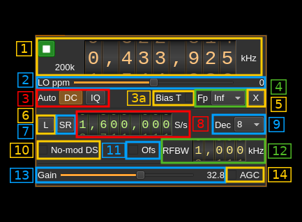
1: Common stream parameters
1.1: Frequency
This is the center frequency of reception in kHz.
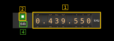
1.2: Start/Stop
Device start / stop button.
- Blue triangle icon: device is ready and can be started
- Green square icon: device is running and can be stopped
- Magenta (or pink) square icon: an error occurred. In the case the device was accidentally disconnected you may click on the icon, plug back in and start again.
1.4: Device or Baseband sample rate
In device sample rate input mode (7) this is the baseband I/Q sample rate in kS/s. This is the device sample rate (8) divided by the decimation factor (9).
In baseband sample rate input mode (7) this is the device I/Q sample rate in kS/s. This is the baseband sample rate (8) multiplied bu the decimation factor (9)
2: Local Oscillator correction
This is the correction to be applied to the local oscillator in ppm.
3: Auto correction options
These buttons control the local DSP auto correction options:
- DC: auto remove DC component
- IQ: auto make I/Q balance. The DC correction must be enabled for this to be effective.
3a: Antenna bias tee
Activates or de-activates the antenna bias tee. Works with v3 dongles only it will be simply ignored by others. It actually activates or de-activates GPIO pin 0 that commands bias tee on v3 dongles.
4: Decimated bandpass center frequency position relative the RTL-SDR center frequency
- Cen: the decimation operation takes place around the RTL-SDR center frequency Fs
- Inf: the decimation operation takes place around Fs - Fc.
- Sup: the decimation operation takes place around Fs + Fc.
With SR as the sample rate before decimation Fc is calculated as:
- if decimation n is 4 or lower: Fc = SR/2^(log2(n)-1). The device center frequency is on the side of the baseband. You need a RF filter bandwidth at least twice the baseband.
- if decimation n is 8 or higher: Fc = SR/n. The device center frequency is half the baseband away from the side of the baseband. You need a RF filter bandwidth at least 3 times the baseband.
5: Transverter mode open dialog
This button opens a dialog to set the transverter mode frequency translation options. The details about this dialog can be found here
6: Toggle low/high sample rate range
When button is on the sample rate can vary from 230 kS/s to 300 kS/s When button is off the sample rate can vary from 950 kS/s to 2400 kS/s
7: Device sample rate / Baseband sample rate input toggle
Use this toggle button to switch the sample rate input next (8) between device sample rate and baseband sample rate input. The button shows the current mode:
- SR: device sample rate input mode. The baseband sample rate (1.4) is the device sample rate (8) divided by the decimation factor (9).
- BB: baseband sample rate input mode. The device sample rate (1.4) is the baseband sample rate (8) multiplied by the decimation factor (9).
8: Sample rate
This is the device sample rate or baseband sample rate in samples per second (S/s). The control (7) is used to switch between the two input modes.
The limits are adjusted automatically. In baseband input mode the limits are driven by the decimation factor (9). You may need to increase this decimation factor to be able to reach lower values.
Use the wheels to adjust the sample rate. Left click on a digit sets the cursor position at this digit. Right click on a digit sets all digits on the right to zero. This effectively floors value at the digit position. Wheels are moved with the mousewheel while pointing at the wheel or by selecting the wheel with the left mouse click and using the keyboard arrows. Pressing shift simultaneously moves digit by 5 and pressing control moves it by 2.
9: Decimation factor
The I/Q stream from the RTLSDR ADC is downsampled by a power of two before being sent to the passband. Possible values are increasing powers of two: 1 (no decimation), 2, 4, 8, 16, 32, 64.
10: Direct sampling mode
Use this checkbox to activate the special RTLSDR direct sampling. This can be used to tune to HF frequencies.
11: Offset tuning
This controls the offset tuning. Some RF frontends like the obsolete E4000 implement this feature and it can seriously reduce the central DC peak without digital correction. This does not work for the R820T and R820T2 that are very popular on which it will produce no effect. However these RF frontends exhibit a central DC peak much smaller than on the E4000 and can be easily corrected digitally via control (3).
12: RF bandwidth
This controls the tuner filter bandwidth and can be varied from 350 kHz to 8 MHz. In practice depending on the value this appears to be larger and the filter center is slightly offset above the center frequency. This can still be very useful to eliminate or attenuate large signals outside the device to host I/Q stream passband.
13: RF gain
The slider sets RF gain in dB. The values are defined in the RTLSDR device and generally are: 0.0, 0.9, 1.4, 2.7, 3.7, 7.7, 8.7, 12.5, 14.4, 15.7, 16.6, 19.7, 20.7, 22.9, 25.4, 28.0, 29.7, 32.8, 33.8, 36.4, 37.2, 38.6, 40.2, 42.1, 43.4, 43.9, 44.5, 48.0, 49.6
14: Automatic Gain Control (AGC)
The AGC checkbox can be used to switch on or off the RTL2838 AGC. This is independent of the gain setting as this AGC acts after the gain block.