16 KiB
##ATV modulator plugin
Introduction
This plugin can be used to generate an analog TV signal mostly used in amateur radio. It is limited to black and white images as only the luminance (256 levels) is supported.
There is no sound either. You could imagine using any of the plugins supporting audio to create a mixed signal. This is not working well however for various reasons. It is better to use two physical transmitters and two physical receivers.
In practice 4 MS/s with about 300 points per line is the lowest sample rate that produces a standard image quality. Lower sample rates and line definition produce low quality images that may still be acceptable for experiments. The plugin offers to go as low as 32 lines and 8 FPS for NBTV experiments. NBTV stands for Narrow Band TeleVision see: Wikipedia article and NBTV.org
Interface
The top and bottom bars of the channel window are described here
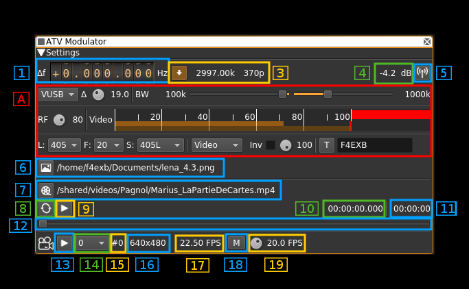
1: Frequency shift from center frequency of transmission
Use the wheels to adjust the frequency shift in Hz from the center frequency of transmission. Left click on a digit sets the cursor position at this digit. Right click on a digit sets all digits on the right to zero. This effectively floors value at the digit position. Wheels are moved with the mousewheel while pointing at the wheel or by selecting the wheel with the left mouse click and using the keyboard arrows. Pressing shift simultaneously moves digit by 5 and pressing control moves it by 2.
3: Sample rate data
The left button can be used to force the rational decimator even when the source and channel sample rates agree. This allows to use the FIR filter of the decimator in any case.
The middle figure is the sample rate in kS/s used by the source which may differ from the channel sample rate which is also the baseband sample rate. If they do not agree the rational interpolator is automatically engaged. This sample rate is calculated as the closest 10 S/s multiple to the channel sample rate to fit an integer number of (virtual) line points. The number of line points accounts for the full line including synchronization. This number is the source sample rate divided by the line frequency. The line frequency is calculated as the nominal number of lines multiplied by the FPS.
S = L×F×n such as B÷10 ≥ S÷10 > (B÷10)−1 where:
- B is the baseband or channel sample rate (they are made the same)
- S is the source sample rate
- L is the number of lines
- F is the number of frames per second
- n is the integer that we call the "number of points"
The right figure is the corresponding number of points and therefore also samples per full line including line synchronization.
Let's take an example with a 405 lines and 20 FPS video signal and a 3000 kS/s sink input sample rate:
- the line frequency is 405 × 25 = 10125 Hz
- 2400 kS/s fit 237.037037037 points per line and therefore is not an integer number
- closest 10 S/s multiple sample rate to fit an integer number of points is 236 × 10125 = 2389.5 kS/s
- therefore decimated sample rate is 2389.5 kS/s and the number of points per line is 236
The example taken in the screenshot is from a 405 lines × 20 FPS video signal:
- source sample rate is 3000 kS/s
- line frequency is 8100 Hz
- 371 points fit in 8100 × 371 = 3005.1 kS/s
- 370 points fit in 8100 × 370 = 2997 kS/s
- therefore the closest sample rate is 2997 kS/s for 370 points per line
☞ For a proper rendering of the image one should aim at having twice the number of points per line relative to the number of lines. This number may be lowered for closeups needing less details like a portrait scene. The less the number of points the less bandwidth the signal takes so as one would expect there is a balance between spectrum efficiency and image quality.
4: Channel power
Average total power in dB relative to a ±1.0 amplitude signal generated in the pass band.
5: Channel mute
Use this button to toggle mute for this channel. The radio waves on the icon are toggled on (active) and off (muted) accordingly. Default is channel active.
A: Signal settings

A.1: Modulation type
The video signal can modulate the carrier in the following modes:
- AM: Amplitude modulation. Modulation index is 90%.
- FM: Frequency modulation. Excursion is a percentage of the bandwidth available given the channel sample rate. This percentage is controlled by button (2). e.g. at 25% for 4 MS/s sample rate this is 1 MHz (±0.5 MHz)
- USB: SSB upper side band: video signal is transposed only in positive frequencies including DC component
- LSB: SSB lower side band: video signal is transposed only in negative frequencies excluding DC component
- VUSB: SSB upper sideband with vestigial lower sideband. The cutoff frequency of the lower sideband is controlled by slider (3)
- VLSB: SSB lower sideband with vestigial upper sideband. The cutoff frequency of the upper sideband is controlled by slider (3)
A.2: FM deviation percentage of total bandwidth
Use this button to control FM deviation in FM modulation mode. This is a percentage of total available channel bandwidth. e.g for the sample rate of 2997 kS/s of the screenshot and a percentage of 19% this yields a full deviation of 2997 × 0.19 = 569.43 kHz that is ±284.715 kHz
☞ You can adjust this value and see the result for yourself. A good starting point is half of the signal bandwidth.
A.3: Opposite sideband FFT filter cutoff
This slider is effective only on SSB and vestigial modes (USB, LSB, VUSB, VLSB). This slider controls the cutoff frequency of the FFT filter in the opposite sideband to the main in band sideband. That is:
- for LSB and VLSB: this is the upper sideband
- for USB and VUSB: this is the lower sideband
The cutoff frequency in kHz is displayed on the left of the slider
A.4: In band filter cutoff
This slider acts on both the FFT filter in SSB modes and the rational decimator FIR filter in other modes.
- AM, FM: this controls the cutoff frequency of the decimator FIR filter.
- USB, LSB, VUSB, VLSB: this controls the cutoff frequency of the FIR filter on the in band side that is:
- upper sideband for USB, VUSB
- lower sideband for LSB, VLSB
The cutoff frequency in kHz is displayed on the right of the slider
A.5: Modulated signal level before filtering stages
This button controls the scaling from the +1/-1 modulated signal level to the -32768/+32768 2 bytes samples. This is useful to control the saturation of the FFT or FIR filters. Looking at the output spectrum you can precisely control the limit above which distortion appears.
A.6: Video signal level meter
This is the level meter fed with the video signal. Units are the percentage of the 0.0 to 1.0 modulating video signal.
A.7: Number of lines
This controls the number of lines per full frame. Choice is between 640, 625, 525, 480, 405, 360, 343, 240, 180, 120, 90, 60 and 32 lines.
A.8: Number of frames per second
This controls the number of full frames per second. Choice is between 30, 25, 20, 16, 12, 10, 8, 5, 2 and 1 frames per second.
☞ Perception of continuous motion is said to be acceptable down to 16 FPS. Down to 8 FPS fluidity is still acceptable. The 5 to 1 FPS modes can be used when you want to transmit images with only few movements or where motion is not important such as fixed webcams. Low FPS will allow for more lines and therefore definition in the same bandwidth.
A.9: TV Standard
This controls the frame synchronization scheme and number of black lines:
- PAL625: this is the PAL 625 lines standard with 25 FPS. Since only black and white (luminance) is supported this corresponds to any of the B,G,I or L PAL standards
- PAL525: this is the PAL 525 lines standard with 30 FPS. This corresponds to the PAL M standard.
- 819L: this is the 819 lines system F (Belgium).
- ShI: this is an experimental mode that uses the least possible vertical sync lines as possible. That is one line for a long synchronization pulse and one line equalizing (short) pulses level to reset the vertical sync condition. Thus only 2 lines are consumed for vertical sync and the rest is left to the image. In this mode the frames are interleaved. In this mode the frames are interleaved and an odd number of lines should be used.
- ShNI: this is the same as above but with non interleaved frames.
- HSkip: this is the horizontal sync skip technique for vertical synchronization. This has been in use in the first TV experiments with a small number of lines. This method just skips one horizontal synchronization pulse to mark the last or the first line (here it is the last). This method does not use any full line for vertical sync and all lines can be used for the image thus it suits the modes with a small number of lines. With more lines however the risk of missing pulses gets higher in adverse conditions because the pulses get shorter and may get swallowed by a stray pulse or a stray pulse can be taken for a valid one. In this case two images might get out of sync instead of just two lines. In practice this is suitable up to 90~120 lines.
☞ Interleaved mode requires an odd number of lines because the system recognizes the even and odd frames depending on a odd or even number of lines respectively for the half images
☞ For non interleaved mode all standards are supposed to work for any number of lines. You may experiment with any and see if it fits your purpose. However it will be easier to obtain good or optimal results in general with the following recommendations:
| #lines | standard |
|---|---|
| 819 | 819L, ShI, ShNI |
| 640 | ShNI |
| 625 | PAL625, PAL525, ShI, ShNI |
| 525 | PAL525, ShI, ShNI |
| 480 | ShNI |
| 405 | ShI, ShNI |
| 360 | ShNI |
| 343 | ShI, ShNI |
| 240 | ShNI |
| 180 | ShNI |
| 120 | ShNI, HSkip |
| 90 | ShNI, HSkip |
| 60 | HSkip |
| 32 | HSkip |
A.10: Input source
This combo box lets you choose between various inputs for the video signal:
- Uniform: the image has a uniform luminance level given by the luminance level adjusted with the button next (10)
- H Bars: horizontal bars from black level on the left to white level on the right
- V Bars: vertical bars from black level on the top to white level on the bottom
- Chess: chessboard pattern alternating black squares and squares with the luminance level adjusted with button (10)
- H Grad: horizontal gradient from black level on the left to white level on the right
- V Grad: vertical gradient from black level on the top to white level on the bottom
- Image: still image read from the file selected with button (13). If no image is selected an uniform image is sent with the luminance adjusted with button (10)
- Video: video file read from the file selected with button (14). If no image is selected an uniform image is sent with the luminance adjusted with button (10). Buttons (15) and (16) control the play.
- Camera: video signal from a webcam or supported video source connected to the system. If no source is selected an uniform image is sent with the luminance adjusted with button (10). Button (21) selects the camera source. Button (20) plays or stops the camera on a still image.
A.11: Video inversion toggle
Use this checkbox to toggle video signal inversion before modulation.
A.12. Luminance level
This button lets you adjust the luminance level of the "blank" screens displays, the lighter squares on the chessboard and the overlay text.
A.13. Overlay text toggle
The button toggles the display of an overlay text on a still image, or a video signal from a file or a camera. Note that for still images you will have to toggle off/on this button to take any change of text or text brightness into account. The brightness level of the text is selected with the luminance adjust button (10). The number of characters is limited to 12.
The text area lets you type a text up to 12 characters.
6. Still picture file select
Clicking on this button will open a file dialog to let you choose an image file for still image display. When the dialog is closed and the choice is validated the name of the file will appear on the space at the right of the button.
7. Video file select
Clicking on this button will open a file dialog to let you choose a video file for video play. When the dialog is closed and the choice is validated the name of the file will appear on the space at the right of the button.
8. Play loop video
Use this button to toggle on/off playing the video file in a loop
9. Play/Pause video
Use this button to toggle on/off the video file play. When play stops the current image is displayed as a still image. When video is stopped the button is dark and a play (►) icon is displayed on the button. When video runs the button is lit and a pause (▋▋) icon is displayed on the button.
10. Current video position
This is the current video file play position in time units relative to the start
11. Video file length
This is the video file play length in time units
12. Video file position slider
This slider can be used to randomly set the current position in the file when file play is in pause state (button 16). When video plays the slider moves according to the current position.
23. Play/Pause camera
Use this button to toggle on/off the camera play. When play stops the current image is displayed as a still image. When camera is stopped the button is dark and a play (►) icon is displayed on the button. When camera runs the button is lit and a pause (▋▋) icon is displayed on the button.
On Linux systems when the play button is engaged for the first time the FPS of the camera is scanned which can take some time (100 frames are read). A message box appears while the operation is running.
14. Camera select
Use this combo to select the camera source when more than one is available. the number corresponds to the index of the camera during the camera scan at the startup of the plugin instance. A maximum of 4 cameras are scanned in whichever order presented by the system.
15. Camera device number
This is the device number used by OpenCV which on Linux systems correspond to the /dev/video device number. i.e. "#0" for /dev/video0.
16. Camera image size
This is the width x height camera image size in pixels
17. System camera FPS
This is the camera FPS. On Windows there is no dynamic FPS check and a fixed 5 FPS is set for each camera. On Linux 90% of the calculated FPS is divided by the number of scanned cameras to give the final FPS. This is an attempt to avoid congestion when multiple cameras are available however this was only tested with two cameras.
18. Manual camera FPS toggle
Use this button to switch between system camera FPS (off) and manual camera FPS (on)
19. Manual camera FPS adjust
Use this dial button to adjust camera FPS manually between 2 and 30 FPS in 0.1 FPS steps. The manual FPS value appears on the right of the button.