7.2 KiB
File Recorder
Introduction
Use this plugin to record its channel IQ data in sdriq or signed 16-bit PCM .wav format. The baseband sample rate can be decimated by a factor of two and its center shifted to accommodate different requirements than recording the full baseband. More than one such plugin can be used in the same baseband to record different parts of the baseband spectrum. Of course in this case file output collision should be avoided.
Such files can be read in SDRangel using the File input plugin.
Each recording is written in a new file with the starting timestamp before the .sdriq extension in yyyy-MM-ddTHH_mm_ss_zzz format. It keeps the first dot limited groups of the filename before the .sdriq or .wav extension if there are two such groups or before the two last groups if there are more than two groups. Examples:
- Given file name:
test.sdriqthen a recording file will be like:test.2020-08-05T21_39_07_974.sdriq - Given file name:
test.2020-08-05T20_36_15_974.sdriqthen a recording file will be like (with timestamp updated):test.2020-08-05T21_41_21_173.sdriq - Given file name:
test.first.sdriqthen a recording file will be like:test.2020-08-05T22_00_07_974.sdriq - Given file name:
record.test.first.sdriqthen a recording file will be like:reocrd.test.2020-08-05T21_39_52_974.sdriq
If a filename is given without .sdriq extension then the .sdriq extension is appended automatically before the above algorithm is applied.
If a filename is given with an extension different of .sdriq or .wav then the extension is replaced by .sdriq automatically before the above algorithm is applied.
Interface
The top and bottom bars of the channel window are described here
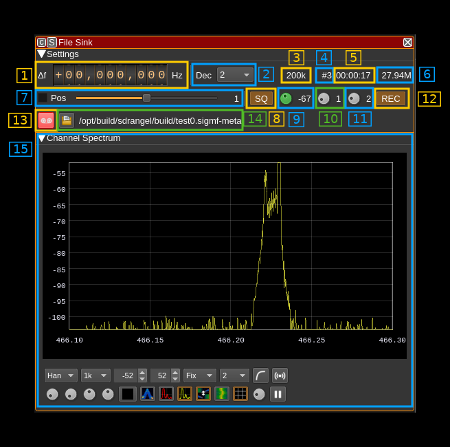
1: Frequency shift from center frequency of reception
Use the wheels to adjust the frequency shift in Hz from the center frequency of reception. Left click on a digit sets the cursor position at this digit. Right click on a digit sets all digits on the right to zero. This effectively floors value at the digit position. Wheels are moved with the mousewheel while pointing at the wheel or by selecting the wheel with the left mouse click and using the keyboard arrows. Pressing shift simultaneously moves digit by 5 and pressing control moves it by 2.
If the fixed position slider is engaged (7) this control is disabled.
2: Decimation factor
Use this control to decimate the baseband samples by a power of two. Consequently the baseband sample rate is reduced by this factor in the channel.
3: Channel (sink) sample rate
Shows the channel sink sample rate in kS/s. The record capture is effectively recorded at this rate.
4: Number of recordings in session
Adding a new File Sink plugin instance or changing the file name starts a new session. This is the number of files recorded in the session (not counting the current one if recording).
5: Recording time
This is the total recording time for the session.
6: Record size
This is the total number of bytes recorded for the session.The number is possibly suffixed by a multiplier character:
- k: kilo for kilobytes
- M: mega for meabytes
- G: giga for gigabytes
7: Fixed frequency shift positions
Use the checkbox to move the shift frequency at definite positions where the chain of half band decimation filters match an exact bandwidth and shift. The effect is to bypass the last interpolator and NCO and thus can save CPU cycles. This may be useful at high sample rates at the expense of not getting exactly on the desired spot.
Use the slider to move position from lower to higher frequency. The position index appears on the right. The higher the decimation factor the more positions are available as the decimated bandwidth gets smaller.
When this is engaged the frequency control (1) is disabled.
This is a GUI only feature when using API it is up to the API client to calculate the desired position. Starting from the center any position lower or higher at the bandwidth divided by two times the decimation factor yields the desired property.
8: Spectrum squelch
Recording can be triggered by specifying a power level. If any peak in the spectrum exceeds this level then recording is triggered. This button only activates the detection system. When squelch is open the level button (9) lits up in green (as on the screenshot). To activate triggered recording you have to use (12).
You can try to see for which squelch level you obtain the desired triggering before actually applying it to control the record process with button (12).
Note that spectrum polling is done every 200 ms. If the signal of interest is shorter you may want to tweak the spectrum controls using the "Maximum" averaging type and a number of averaging samples making the averaging period (appearing in the tooltip) larger than 200 ms. Please refer to spectrum controls documentation in the main window readme (link in 15) for more details.
9: Squelch level
This is the squelch level as discussed above. To try to find the correct value you can use the spectrum display (15).
10: Pre recording period
This is the number of seconds of data that will be prepended before the start of recording point. Thus you can make sure that the signal of interest will be fully recorded. Works in both spectrum squelch triggered and manual mode.
11: Post recording period
This applies to spectrum squelch triggered recording only. This is the number of seconds recorded after the squelch closes. If the squelch opens again during this period then the counter is reset and recording will stop only after this period of time is elapsed without the squelch re-opening.
This is useful if you want to record a bunch of transient bursts or just make sure that the recording does not stop too abruptly.
12: Enable/disable spectrum squelch triggered recording
Use this button to effectively apply spectrum squelch to recording. In this mode recording on and off will be under the control of the squelch system. Thus when active the normal record button (13) is disabled. However its color changes to reflect the recording status as described next.
13: Record button
Use this button to start/stop recording unconditionally. Note that start/stop recording is opening/closing a new file in the same session. Until the file is changed with (14) the same file root will be used until the device is stopped or channel plugin is dismissed.
The button turns red if recording is active.
14: Select output file
Use this button to open a file dialog that lets you specify the location and name of the output files. Please refer to the indtroduction at the top of this page for details on how the recording file name is composed from the given file name.
The file path currently being written (or last closed) appears at the right of the button.
15: Channel spectrum
This is the spectrum display of the IQ stream seen by the channel. Details on the spectrum view and controls can be found here