8.5 KiB
SSB/DSB demodulator plugin
Introduction
This plugin can be used to listen to a single sideband or double sidebands modulated signal.
Interface
The top and bottom bars of the channel window are described here
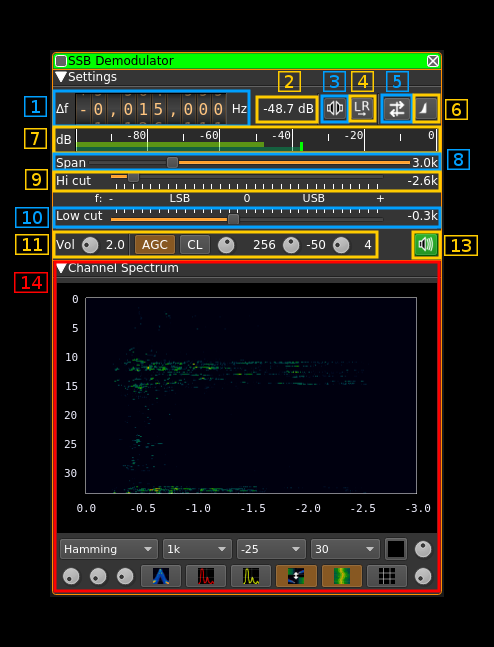
☞ In order to toggle USB or LSB mode in SSB mode you have to set the "BW" in channel filter cutoff control (9) to a positive (USB) or negative (LSB) value. The above screenshot shows a LSB setup. See the (8) to (10) paragraphs below for details.
☞ The channel marker in the main spectrum display shows the actual band received taking in channel filtering into account.
1: Frequency shift from center frequency of reception
Use the wheels to adjust the frequency shift in Hz from the center frequency of reception. Left click on a digit sets the cursor position at this digit. Right click on a digit sets all digits on the right to zero. This effectively floors value at the digit position. Wheels are moved with the mousewheel while pointing at the wheel or by selecting the wheel with the left mouse click and using the keyboard arrows. Pressing shift simultaneously moves digit by 5 and pressing control moves it by 2.
2: Channel power
Average total power in dB relative to a +/- 1.0 amplitude signal received in the pass band.
3: Monaural/binaural toggle
- Monaural: the scalar signal is routed to both left and right audio channels
- Binaural: the complex signal is fed with the real part on the left audio channel and the imaginary part to the right audio channel
4: Invert left and right channels
Inverts left and right audio channels. Useful in binaural mode only.
5: Sideband flip
Flip LSB/USB. Mirror filter bandwidth around zero frequency and change from LSB to USB or vice versa. Works in SSB mode only.
6: SSB/DSB demodulation
Toggles between SSB (icon with one sideband signal) and DSB (icon with double sidebands signal). In SSB mode the shape of the icon represents LSB or USB operation.
7: Level meter in dB
- top bar (green): average value
- bottom bar (blue green): instantaneous peak value
- tip vertical bar (bright green): peak hold value
8: Spectrum display frequency span
The audio sample rate SR is further decimated by powers of two for the spectrum display and in channel filter limits. This effectively sets the total available bandwidth depending on the decimation:
- 1 (no decimation): SR/2 (SSB) or SR (DSB)
- 2: SR/4 (SSB) or SR/2 (DSB)
- 4: SR/8 (SSB) or SR/4 (DSB)
- 8: SR/16 (SSB) or SR/8 (DSB)
- 16: SR/32 (SSB) or SR/16 (DSB)
The span value display is set as follows depending on the SSB or DSB mode:
- In SSB mode: the span goes from zero to the upper (USB: positive frequencies) or lower (LSB: negative frequencies) limit and the absolute value of the limit is displayed.
- In DSB mode: the span goes from the lower to the upper limit of same absolute value and ± the absolute value of the limit is displayed.
This is how the Span (8) and bandpass (9, 10) filter controls look like in the 3 possible modes:
DSB:
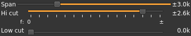
- Decimation factor is 4 hence span is 6 kHz from -3 to +3 kHz and ±3.0k is displayed
- In channel filter bandwidth is 5.2 kHz from -2.6 to +2.6 kHz and ±2.6k is displayed
- In channel filter "low cut" is disabled and set to 0
USB:
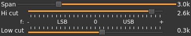
- Decimation factor is 4 hence span is 3 kHz from 0 to 3 kHz and 3.0k is displayed
- In channel filter upper cutoff is 2.6 kHz and 2.6k is displayed
- In channel filter lower cutoff is 0.3 kHz and 0.3k is displayed
- Hence in channel filter bandwidth is 2.3 kHz
LSB:
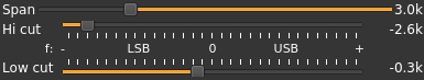
- Decimation factor is 4 hence span is 3 kHz from 0 to -3 kHz and 3.0k is displayed
- In channel filter lower cutoff is -2.6 kHz and -2.6k is displayed
- In channel filter upper cutoff is -0.3 kHz and -0.3k is displayed
- Hence in channel filter bandwidth is 2.3 kHz
9: "BW": In channel bandpass filter cutoff frequency farthest from zero
Values are expressed in kHz and step is 100 Hz.
- In SSB mode this is the upper (USB: positive frequencies) or lower (LSB: negative frequencies) cutoff of the in channel single side band bandpass filter. The value triggers LSB mode when negative and USB when positive
- In DSB mode this is half the bandwidth of the double side band in channel bandpass filter therefore the value is prefixed with the ± sign.
10: "Low cut": In channel bandpass filter cutoff frequency closest to zero
Values are expressed in kHz and step is 100 Hz.
- In SSB mode this is the lower cutoff (USB: positive frequencies) or higher cutoff (LSB: negative frequencies) of the in channel single side band bandpass filter.
- In DSB mode it is inactive and set to zero (double side band filter).
11: Volume and AGC
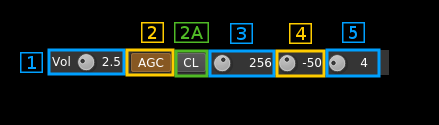
11.1: Volume
This is the volume of the audio signal in dB from 0 (no gain) to 40 (10000). It can be varied continuously in 1 dB steps using the dial button. When AGC is engaged it is recommended to set a low value in dB not exceeding 3 db (gain 2). When AGC is not engaged the volume entirely depends on the RF power and can vary in large proportions. Hence setting the value in dB is more convenient to accommodate large differences.
11.2: AGC toggle
Use this checkbox to toggle AGC on and off.
If you are into digging weak signals out of the noise you probably will not turn the AGC on. AGC is intended for medium and large signals and help accommodate the signal power variations from a station to another or due to QSB.
This AGC is based on the calculated magnitude (square root of power of the filtered signal as I² + Q²) and will try to adjust audio volume as if a -20dB power signal was received.
11.2A: AGC clamping
When on this clamps signal at the maximum amplitude. Normally this is not needed for most signals as the AGC amplitude order is quite conservative at 10% of the maximum. You may switch it on if you notice a loud click when a transmission starts.
11.3: AGC time constant
This is the time window in milliseconds of the moving average used to calculate the signal power average. It can be varied in powers of two from 16 to 2048 ms that is: 16, 32, 64, 128, 256, 512, 1024 and 2048 ms. The most practical values are between 128 and 512 ms.
11.4: Signal power threshold (squelch)
Active only in AGC mode.
This threshold acts as a squelch and will mute the sound below this average signal power. To prevent short transient drop outs the squelch gets active only if the power has been below the threshold for a period equal to the AGC time constant (11.3)
This feature is mostly useful when more than one SSB channel is active. When there is no transmission the level of noise rises at the level of a normal signal due to the AGC and adds to the noise of other channels. Therefore it is desirable to shut down the audio when there is no signal in the channel.
To turn off the squelch completely move the knob all the way down (left). Then "---" will display as the value and the squelch will be disabled.
The signal power is calculated as the moving average over the AGC time constant (11.3) of the power of the filtered signal as I² + Q².
11.5: Signal power threshold (squelch) gate
Active only in AGC mode with squelch enabled.
To avoid unwanted squelch opening on short transient bursts only signals with power above threshold during this period in milliseconds will open the squelch.It can be varied from 0 to 20 ms in 1 ms steps then from 30 to 500 ms in 10 ms steps.
When the power threshold is close to the noise floor a few milliseconds help in preventing noise power wiggle to open the squelch.
13: Audio mute and audio output select
Left click on this button to toggle audio mute for this channel.
If you right click on it a dialog will open to select the audio output device. See audio management documentation for details.
14: Spectrum display
This is the spectrum display of the demodulated signal (SSB) or translated signal (DSB). Controls on the bottom of the panel are identical to the ones of the main spectrum display. Details on the spectrum view and controls can be found here