15 KiB
ATV demodulator plugin
Introduction
This plugin can be used to view amateur analog television transmissions a.k.a ATV. The transmitted video signal can be black and white or color (PAL, NTSC) but only the black and white level (luminance) is retained and hence image is black and white. There is no provision to demodulate the audio subcarrier either. The modulation can be either AM or FM (SSB with carrier is only experimental). A plugin supporting audio can be used in the same passband to demodulate an audio carrier but this does not work for a subcarrier which excludes FM.
An optional rational downsampler with lowpass filtering can be used but its ratio is always 1.0 so in fact only the filter functionality is retained. This is a provision for future developments. When this downsampler is not engaged (button A.3) the source feeds the channel directly. A standard image quality for broadcast standard modes requires a sample rate of at least 4 MS/s. The Airspy Mini 3 MS/s mode may still be acceptable.
Experimental modes with smaller number of lines and FPS values can be used in conjunction with the ATV Modulator plugin to reduce sample rate and occupied bandwidth. Very low line frequencies and thus small bandwidths are reachable with degraded image quality. This is known as NBTV see: Wikipedia article and NBTV.org
Interface

The interface is divided into three collapsable sections:
- A: the RF settings
- B: the video settings
- C: the video monitor and scope in a tabbed panel arrangement
Each part is detailed next
A: RF settings

1: Frequency shift from center frequency of reception direction
The "+/-" button on the left side of the dial toggles between positive and negative shift.
2: Frequency shift from center frequency of reception value
Use the wheels to adjust the frequency shift in Hz from the center frequency of reception. Left click on a digit sets the cursor position at this digit. Right click on a digit sets all digits on the right to zero. This effectively floors value at the digit position.
3: Rational downsampler toggle
Use this toggle button to enable or disable the rational downsampler and its FIR filter. Without downsampling the source plugin feeds the channel directly.
When the downsampler is engaged the signal is lowpass filtered and the cutoff frequency can be adjusted with the in band filter cutoff slider (13).
4: Channel sample rate
This is the channel sample rate in kS/s. For good horizontal synchronization you should aim at a sample rate (given by the source) that yields an integer number of points per line. Sample rate (S), number of lines (l) and frames per second (F) should yield an integer number of points (N) using this formula:
N = S / (l × F)
☞ The number of points should be a bit larger than the number of lines up to 240 lines then it can be a bit smaller to give an acceptable image quality.
When the rational dowsampler is engaged (3) the resulting sample rate is calculated as the closest 10 S/s multiple to the source sample rate to fit an integer number of line points.
The example taken in the screenshot is from a 405 lines × 20 FPS video signal:
- source sample rate is 1500 kS/s
- line frequency is 8100 Hz
- 186 points fit in 8100 × 186 = 1506.6 kS/s
- 185 points fit in 8100 × 185 = 1498.5 kS/s
- therefore the closest sample rate is 1498.5 kS/s for 185 points per line
5: Number of points (or samples) per line
This is the number of points or samples per complete line including sync and padding. This is derived from the sample rate and line frequency as the ratio of the two. For example with a 625 lines × 25 FPS signal the line frequency is 15625 Hz. If the channel sample rate is 1500 kS/s this yields 1500000/15625 = 96 points. If the ratio is not an integer then the integer part is taken.
6: BFO PLL lock indicator
⚠ this is experimental.
When single sideband demodulation is selected (USB, LSB) the BFO is phased locked to the carrier. This indicator turns green if the PLL is locked.
7: BFO frequency adjustment
⚠ this is experimental.
This allows adjstment of BFO frequency in 1 Hz steps from -2 to +2 kHz. You will have to look for the right value to lock to the carrier. See (6) for the lock indicator. This will work only at relatively low sample rates say below 1 MS/s.
The BFO base frequency in Hz appears on the right. Actual frequency may change acoording to PLL locking to the carrier.
8: Channel power
Average total power in dB relative to a ±1.0 amplitude signal generated in the pass band.
9: Modulation
- FM1: this is Frequency Modulation with approximative demodulation algorithm not using atan2
- FM2: this is Frequency Modulation with less approximative demodulation algorithm still not using atan2
- FM3: this is Frequency Modulation with atan2 approximation for phase calculation and then a discrete differentiation is applied
- AM: this is Amplitude Modulation
- USB: ⚠ USB demodulation synchronous to the carrier (experimental)
- LSB: ⚠ LSB demodulation synchronous to the carrier (experimental)
For FM choose the algorithm that best suits your conditions.
☞ only FM3 is accurate with regard to FM deviation (see 10).
⚠ USB and LSB modes are experimental and do not show good results for sample rates greater than 1 MS/s. Adjusting the BFO can be picky and unstable.
10: FM deviation adjustment
Using this button you can adjust the nominal FM deviation as a percentage of the channel bandwidth that is displayed on the right of the button. When a signal with this deviation is received the demodulated signal is in the range -0.5/+0.5 which is shifted to a 0/1 range video signal.
☞ The value is accurate only with the atan2 differential demodulator i.e. FM3. With FM1 and FM2 you will have to adjust it for best image results. You can use the scope as an aid to try to fit the video signal in the 0/1 range.
11: FFT asymmetrical filter toggle
Use this button to enable/disable the FFT asymmetrical filter. Use this filter when you want to optimize the reception of vestigial sideband AM signals.
12: FFT asymmetrical filter opposite band cutoff frequency
For all modulations except LSB this is the lower side band.
This slider lets you adjust the opposite band cutoff frequency of the FFT asymmetrical filter. The value in kHz appears on the left of the slider.
13: FFT asymmetrical filter in band cutoff frequency
For all modulations except LSB this is the upper side band.
This slider lets you adjust the in band cutoff frequency of the FFT asymmetrical filter. The value in kHz appears on the left of the slider.
If the rational downsampler is engaged (3) this slider also controls the downsampler cutoff frequency.
B: Video settings

1: Nominal number of lines
This is the total number of lines including all possible synchronization signals.
Choice is between 640, 625, 525, 480, 405, 360, 343, 240, 180, 120, 90, 60 and 32 lines. The actual number of image lines depends on the synchronization scheme.
2: Frames Per Second
This combo lets you chose between a 30, 25, 20, 16, 12, 10, 8, 5, 2 and 1 FPS. This is the resulting FPS. In interleaved modes the half frame rate is doubled.
☞ Perception of continuous motion is said to be acceptable down to 16 FPS. Down to 8 FPS fluidity is still acceptable. The 5 to 1 FPS modes can be used for transmission of images with only few movements or where motion is not important such as fixed webcams. Low FPS will allow for more lines and therefore definition in the same bandwidth.
3: Synchronization standard
This combo lets you set the TV standard type. This sets the number of lines per complete image, frame synchronization parameters and number of blank (black) lines. Choice is between:
- PAL625: this is based on the classical 625 lines PAL system. It uses 7 or 8 synchronization lines depending on the half frame (field). It has also 17 black lines on the top of each half frame.
- PAL525: the only difference with PAL625 is the number of black lines which is down to 15
- PAL405: this is not the British standard. It just follows the same scheme as the two above but with only 7 black lines per half frame
- ShI: this is an experimental mode that uses the least possible vertical sync lines as possible. That is one line for a long synchronization pulse and one line at a higher level (0.7) to reset the vertical sync condition. Thus only 2 lines are consumed for vertical sync and the rest is left to the image. In this mode the frames are interleaved
- ShNI: this is the same as above but with non interleaved frames.
- HSkip: this is the horizontal sync skip technique for vertical synchronization. This has been in use in the first TV experiments with a small number of lines. This method just skips one horizontal synchronization pluse to mark the last or the first line (here it is the last). This method does not use any full line for vertical sync and all lines can be used for the image thus it suits the modes with a small number of lines. With more lines however the risk of missing pulses gets higher in adverse conditions because the pulses get shorter and may get swallowed by a stray pulse or a stray pulse can be taken for a valid one. In this case two images might get out of sync instead of just two lines. In practice this is suitable up to 90~120 lines.
When the standard chosen matches the standard of transmission the image should appear in full size and proper aspect ratio.
☞ Interleaved mode requires an odd number of lines because the system recognizes the even and odd frames depending on a odd or even number of lines respectively for the half images
☞ For non interlaved mode all standards are supposed to work for any number of lines. You may experiment with any and see if it fits your purpose. However it will be easier to obtain good or optimal results in general with the following recommendations:
| #lines | standard |
|---|---|
| 640 | ShNI |
| 625 | PAL625, PAL525, PAL405 |
| 525 | PAL525, PAL405 |
| 480 | ShNI |
| 405 | PAL405, ShI, ShNI |
| 360 | ShNI |
| 343 | ShI, ShNI |
| 240 | ShNI |
| 180 | ShNI |
| 120 | ShNI, HSkip |
| 90 | ShNI, HSkip |
| 60 | HSkip |
| 32 | HSkip |
4: Horizontal sync
Check/uncheck this box to toggle horizontal synchronization processing.
5: Vertical sync
Check/uncheck this box to toggle vertical synchronization processing.
6: Invert video
Check/uncheck this box to toggle video signal inversion. This does not work well in AM for now.
7: Half frames
Check this box to render only half of the frames for slow processors.
8: Reset defaults
Use this push button to reset values to a standard setting:
- FM1 modulation
- 625 lines
- 25 FPS
- PAL625 standard
- Horizontal and vertical syncs active
- No video inversion
- Interleaving
- 100 mV sync level
- 310 mV black level
- 64 microsecond line length (middle)
- 4.7 microsecond sync pulse length (middle)
9: Synchronization level
Use this slider to adjust the top level of the synchronization pulse on a 0 to 1V scale. The value in mV appears on the right of the slider. Nominal value: 100 mV.
10: Black level
Use this slider to adjust the black level of the video signal on a 0 to 1V scale. The value in mV appears on the right of the slider. Nominal value: 310 mV.
11: Line length
This is the line length in time units. The value appears on the right of the slider. Nominal value depends on the nominal line frequency. For example with 405 lines and 20 FPS. The line frequency is 405 × 20 = 8100 Hz thus the nominal line time is the inverse of this value that is ≈123.45 μs
The slider step is set to a sample period in order to ensure that the adjustment is done with the best possible precision. For example at 1500 kS/s sample rate this will be the inverse of this value that is ≈666.67 ns. The middle position of the slider sets the nominal value and the slider step appears in the tooltip.
12: Horizontal synchronization pulse length
This is the length in time units of a horizontal or line synchronization pulse. The value appears on the right of the slider. Nominal value depends on the nominal line length as described above. The nominal pulse length is derived from the 4.7 μs pulse of a 625 lines standard system with a 64 μs line length. For example with a 405 lines × 20 FPS transmission that has a line length of ≈123.45 μs this is (4.7 / 64) × 123.45 ≈ 9.07 μs. In practice you will adjust it to a slightly smaller value to be able to synchronize.
Similarly to the line length slider the slider step is set to a sample period in order to ensure that the adjustment is done with the best possible precision. The middle position of the slider sets the nominal value and the slider step appears in the tooltip.
☞ You can move this control back and forth in case you have synchronizing issues as it can help the synchronization system to get back into pace.
C: Image
Monitor
Select monitor with the monitor tab on the left side.
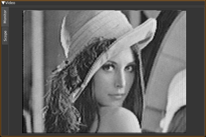
This is where the TV image appears. Yes on the screenshot this is the famous Lenna. The original image is 512 × 512 pixels so it has been cropped to fit the 4:3 format. The screen geometry ratio is fixed to 4:3 format. You will have to choose the standard (B.3) matching the transmission to ensure that the transmitted image fits perfectly.
Scope
Select scope with the scope tab on the left side.
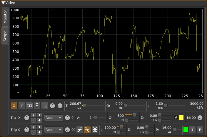
This is a scope widget fed with the video signal. Controls of the scope are the same as with the ChannelAnalyzerNG plugin. Please refer to this plugin for more details.
Note that the video signal is a real signal so the imaginary part is always null. Therefore only the "Real" mode for both the trace and the trigger is interesting.