I often find that I want to instrument things (like ISR routines) so I get some detailed timing information. So I thought I would document the process I use.
###Initialize the Pins###
I typically use pins X1, X2, X3, and X4, because they happen to correspond to CPU pins A0, A1, A2, and A3. We need to initialize the pins as outputs. A reasonable place to put the initialization code is in main.c, just after the GPIO clocks are initialized (search for __GPIOD_CLK_ENABLE). The following snippet is what I would use to initialize 4 pins:
    GPIO_InitTypeDef GPIO_InitStructure;
    GPIO_InitStructure.Mode = GPIO_MODE_OUTPUT_PP;
    GPIO_InitStructure.Pull = GPIO_NOPULL;
    GPIO_InitStructure.Speed = GPIO_SPEED_HIGH;
    GPIO_InitStructure.Alternate = 0;
    GPIO_InitStructure.Pin = GPIO_PIN_0 | GPIO_PIN_1 | GPIO_PIN_2 | GPIO_PIN_3;
    HAL_GPIO_Init(GPIOA, &GPIO_InitStructure);
main.c already includes enough headers that nothing extra is needed for the above.
###Toggle the pins###
Let's suppose that I want to instrument the IRQ Handler for UART6. In the stm32_it.c file, we'll need to pull in some header files. So add the following #includes:
#include "py/mphal.h"
#include "pin.h"
#include "genhdr/pins.h"
and now we can toggle a GPIO in the ISR handler like so:
void USART6_IRQHandler(void) {
    GPIO_set_pin(pin_A0.gpio, pin_A0.pin_mask);
    uart_irq_handler(6);
    GPIO_clear_pin(pin_A0.gpio, pin_A0.pin_mask);
}
###Capture###
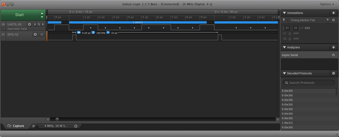
Here's what a typical capture might look like. This was done using the above code and captured while receiving UART data at 1 Mbit/sec.