15 KiB
1. Incremental encoders
These simple devices conceal a number of subtleties and have been the subject of lengthy debate in the MicroPython forum. This doc aims to resolve the issues and to offer tested solutions.
There are three technologies that I am aware of:
- Optical.
- Magnetic.
- Mechanical (using switch contacts).
All produce quadrature signals looking like this:
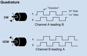
consequently the same code may be used regardless of encoder type.
They have two primary applications:
- Shaft position and speed measurements on machines.
- Control knobs for user input. For user input a mechanical device, being inexpensive, usually suffices. See this Adafruit product.
In applications such as NC machines longevity and reliability are paramount: this normally rules out mechanical devices. Rotational speed is also likely to be too high. In machine tools it is vital to maintain perfect accuracy over very long periods. This may impact the electronic design of the interface between the encoder and the host. High precision comes at no cost in code, but there may be issues in devices with high interrupt latency such as ESP32, especially with SPIRAM.
The ideal host, especially for precison applications, is a Pyboard. This is because Pyboard timers can decode in hardware, as shown in this script from Dave Hylands. Hardware decoding eliminates all concerns over interrupt latency or input pulse rates.
2. Basic encoder script
This illustrates the basic algorithm used in these drivers, which is the simplest and fastest way I know. In practice the interrupt service routines are slightly more complex for reasons discussed below, but this code can be run on any MicroPython platform. Note the adaptation for platforms that don't support hard IRQ's.
from machine import Pin

class Encoder:
    def __init__(self, pin_x, pin_y, scale=1):
        self.scale = scale
        self.pin_x = pin_x
        self.pin_y = pin_y
        self._pos = 0
        try:
            self.x_interrupt = pin_x.irq(trigger=Pin.IRQ_RISING | Pin.IRQ_FALLING, handler=self.x_callback, hard=True)
            self.y_interrupt = pin_y.irq(trigger=Pin.IRQ_RISING | Pin.IRQ_FALLING, handler=self.y_callback, hard=True)
        except TypeError:
            self.x_interrupt = pin_x.irq(trigger=Pin.IRQ_RISING | Pin.IRQ_FALLING, handler=self.x_callback)
            self.y_interrupt = pin_y.irq(trigger=Pin.IRQ_RISING | Pin.IRQ_FALLING, handler=self.y_callback)

    def x_callback(self, pin_x):
        forward = pin_x() ^ self.pin_y()
        self._pos += 1 if forward else -1

    def y_callback(self, pin_y):
        forward = self.pin_x() ^ pin_y() ^ 1
        self._pos += 1 if forward else -1

    def position(self, value=None):
        if value is not None:
            self._pos = round(value / self.scale)
        return self._pos * self.scale
If the direction is incorrect, transpose the X and Y pins in hardware or in the constructor call.
Contrary to common opinion a state table is not necessary to produce a correct algorithm: see section 7.
3. Problem 1: Interrupt latency
By default, pin interrupts defined using the machine module are soft. This
introduces latency if a line changes state when a garbage collection is in
progress. The above script attempts to use hard IRQ's, but not all platforms
support them (notably ESP8266 and ESP32).
4. Problem 2: Jitter
The picture above is idealised. In practice it is possible to receive a succession of edges on one input line, with no transitions on the other. On mechanical encoders this may be caused by contact bounce. On any type it can result from vibration, where the encoder happens to stop at an angle exactly matching an edge. An arbitrarily long sequence of pulses on one line is the result. A correct algorithm must be able to cope with this: the outcome will be one digit of jitter in the output count but no systematic drift.
In practice the frequency of such edges may be arbitrarily high. This imposes a need for synchronisation to limit the possible rate if bit-perfect results are required. In any solution based on interrupts it is necessary to avoid the condition where multiple pulses arrive during the latency period.
4.1 Synchronisation
Decoders of all types (including hardware implementations) can fail if edges on one line occur at too high a rate: transitions can be missed leading to a gradual drift of measured count compared to actual position. With an encoder that produces good logic levels the solution is to limit the rate by pre-synchronising the digital signals to a clock. For bit-perfect results a single level of clock synchronisation is inadequate because of metastability. Typically two levels are used. See this Wikipedia article.
The clock rate of a synchroniser for a software decoder must be chosen with regard to the worst-case latency of the host. The clock rate will then determine the maximum permissible rotation speed of the encoder.
Contact bounce on mechanical encoders can also result in invalid logic levels. This can cause a variety of unwanted results: conditioning with a CR network and a Schmitt trigger should be considered. That said, remarkably accurate tracking can be achieved in code.
Where bit-perfect results are required the simplest approach is to use a target which supports hardware decoding and which pre-synchronises the signals. STM32 meets these criteria.
5. Problem 3: Concurrency
The presented code samples use interrupts in order to handle the potentially
high rate at which transitions can occur. The above script maintains a
position value ._pos which can be queried at any time. This does not present
concurrency issues because changes to an integer are atomic.
However some applications, notably in user interface designs, may require an encoder action to trigger complex behaviour. The obvious solution would be to adapt the script to do this by having the two ISR methods call a function. However the function would run in an interrupt context which (even with soft IRQ's) presents concurrency issues where an application's data can change at any point in the application's execution. Further, a complex function would cause the ISR to block for a long period which is bad practice.
The use of micropython.schedule avoids the problem of excessive ISR blocking
but would not solve the concurrency issue described above.
A solution to this is an interface between the ISR's and uasyncio whereby the
ISR's set a ThreadSafeFlag. This is awaited by a uasyncio Task which runs
a user supplied callback. The latter runs in a uasyncio context: the state of
any Task can only change at times when it has yielded to the scheduler in
accordance with uasyncio rules. This is implemented in
this asynchronous driver.
This also handles the case where a mechanical encoder has a large number of
states per revolution. The driver has the option to divide these down, reducing
the rate at which callbacks occur.
6. Code samples
encoder_portable.pySuitable for most purposes.encoder_timed.pyProvides rate information by timing successive edges. In practice this is likely to need filtering to reduce jitter caused by imperfections in the encoder geometry. With a mechanical knob turned by an anthropoid ape it's debatable whether it produces anything useful :)encoder_rp2.pyVersion specific to Raspberry Pico RP2 chip. This uses the PIO and Viper code to achieve fast response - upto ~10K transitions/s.- Asynchronous driver
for
uasyncioapplications.
For mechanical encoders consider the need for pull up or pull down resistors.
Applications which just require the maintenance of a position count would
normally use encoder_portable.py. Where callbacks are required, or tracking
of detent positions is needed, the asynchronous driver is preferred for reasons
covered in this document.
7. Algorithm
Discussions on the MicroPython forum demonstrate a degree of confusion about the merits of different decoding algorithms and about contact debouncing. These notes aim to clarify the issues and to provide an explanation for the approach used in my code samples; also to describe the mechanism where errors occur.
Incremental encoders produce two signals x and y. Possible state changes
are shown in this state diagram.
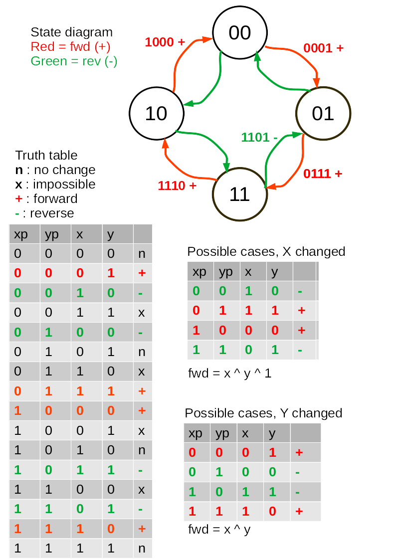
The truth table includes the previous (xp and yp) and current (x and y)
values of the signals. It includes all logically possible combinations of these
signals. These include cases where no change occurs (marked n) and cases
which are physically impossible (x). The latter arise because both signals
cannot change state simultaneously.
Decoding these four bits is a problem of combinatorial logic. All such problems
may be solved by using the bits as addresses of a lookup table. In this case
there would be two output bits signifying increment, decrement or do nothing.
However, simplifications are possible if changes of x and y trigger
interrupts (i.e. interrupt on IRQ_RISING | IRQ_FALLING).
The truth table may then be split into two, one catering for cases where x
has changed, and the other for y changes. The illegal cases are discarded and
the "no change" cases will not trigger an interrupt. All cases in these tables
cause a change in position and inspection shows that the direction is the
exclusive or of the current x and y values, with opposite polarity for
the x and y interrupts.
7.1 Debouncing
Contact bounce or vibration effects cause an oscillating signal on one line. The state diagram shows that this is logically indistinguishable from a physical movement of the encoder backwards and forwards across one transition point. Consequently any valid decoding algorithm will register a change in position of one LSB forwards and backwards. There is no systematic drift, just one LSB of positional uncertainty.
7.2 Algorithm quality
All valid solutions to a combinatorial logic problem are equivalent. The only ways in which one solution can be considered "better" than another are in qualities such as performance and code size. Where decoders can differ in quality is in their handling of interrupts. The approach used in the Asynchronous driver has the following characteristics:
- Interrupt service routines are minimal.
- Encoders with 2 or 4 pulses per detent are handled by selection of a single integer.
- The algorithm doesn't care about the polarity of the encoder signals.
7.3 Interrupt issues
As discussed above, any solution will have a limit to the rate at which edges can be tracked. This section describes the limits of a MicroPython interrupt-driven solution and the way in which incorrect counts can arise.
Interrupts suffer from latency: there is a time delay between an edge occurring and the ISR executing. The magnitude depends on what is running at the moment the edge occurs and consequently varies in real time. Another ISR may be running. Higher priority interrupts may be pending service. In the case of soft IRQ's garbage collection may be in progress.
Consider the following ISR:
    def x_callback(self, pin_x):
        forward = pin_x() ^ self.pin_y()
        self._pos += 1 if forward else -1
This is necessarily triggered by either edge on pin_x. While .pin_y should
be stable when an edge occurs on pin_x, the state of pin_x may have changed
by the time the latency has elapsed and the ISR reads its value. In this case
the change will be registered with the wrong direction.
This is handled by the following adaptation:
    def x_callback(self, pin_x):
        if (x := pin_x()) != self._x:
            self._x = x
            self._v += 1 if x ^ self._pin_y() else -1
If an interrupt occurs and no change has taken place since the previous one, it is ignored on the basis that a second edge must have occurred during the latency period. That second edge will trigger another interrupt which will be ignored for the same reason.
While this works remarkably well with a mechanical encoder connected directly, it cannot be expected to handle multiple transitions during the latency period. If bit-perfect results are required, hardware rate limiting must be applied.
7.4 Encoders with mechanical detents
Encoders intended for user controls often have detents with each "click"
producing one complete cycle of the state transition diagram above. If it is
required to track these exactly, for example triggering a callback on each
"click", the
asynchronous driver
with a division ratio of 4. Some encoders, described as "half step", have two
detents per revolution. These can be handled by setting div=2 on this driver.
It is almost certainly impossible to provide exact tracking on platforms which support only soft IRQ's because garbage collection results in interrupt latency which exceeds the time between edges from the encoder. On platforms with SPIRAM GC can take hundreds of ms.
8. Preconditioning and rate limiting
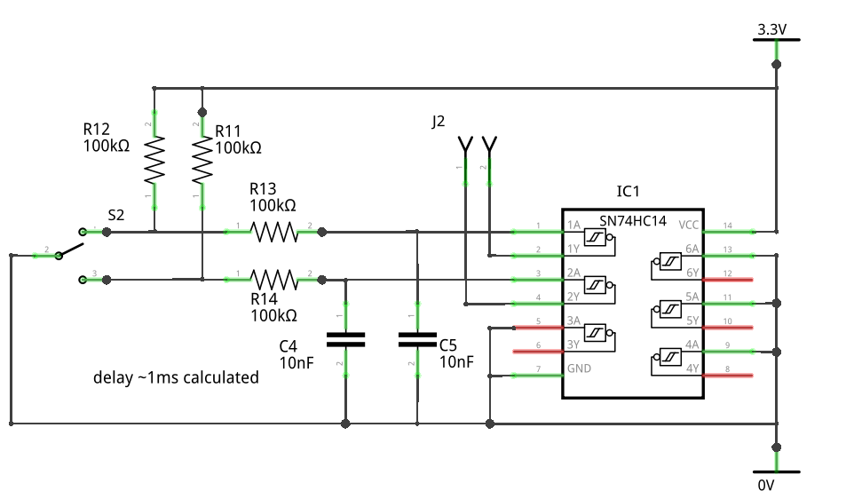
8.1 Mechanical encoders
The task here is to ensure valid logic levels in addition to limiting the pulse rate. The solution is to use a single pole low pass filter to limit the rate, followed by a Schmitt trigger to guarantee logic levels. In practice a time constant of 1-1.5ms is sufficient for platforms with hard IRQ's.
Typical circuit. The asymmetry in the timing resistors approximately matches
the offsets of the chip's threshold voltages.
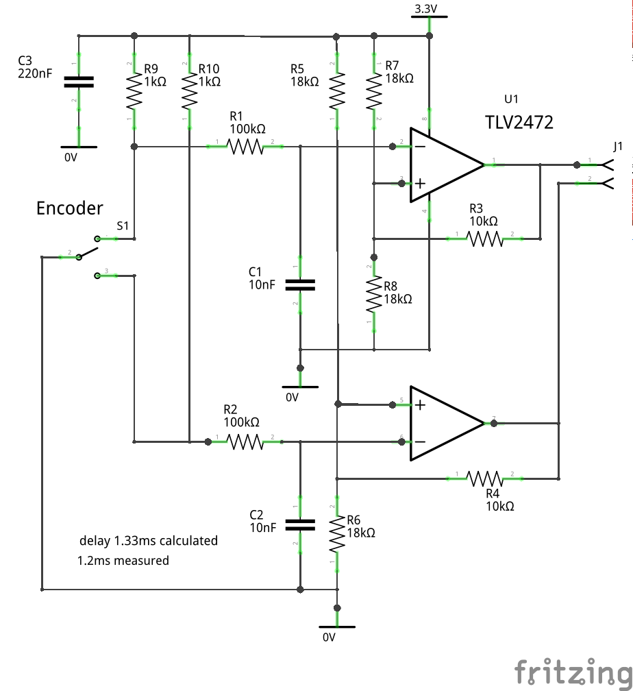
Alternative using a dual CMOS op amp.
8.2 Optical encoders
These can use the above circuits, but as they produce good logic levels an alternative is to use two d-type flip-flops on each channel, clocked using a signal from the host. Typically this might be produced by a PWM channel running continuously. Clock rate depends on the expected worst-case interrupt latency.
This Wikipedia image illustrates the idea, along with the metastability problem discussed in the article.
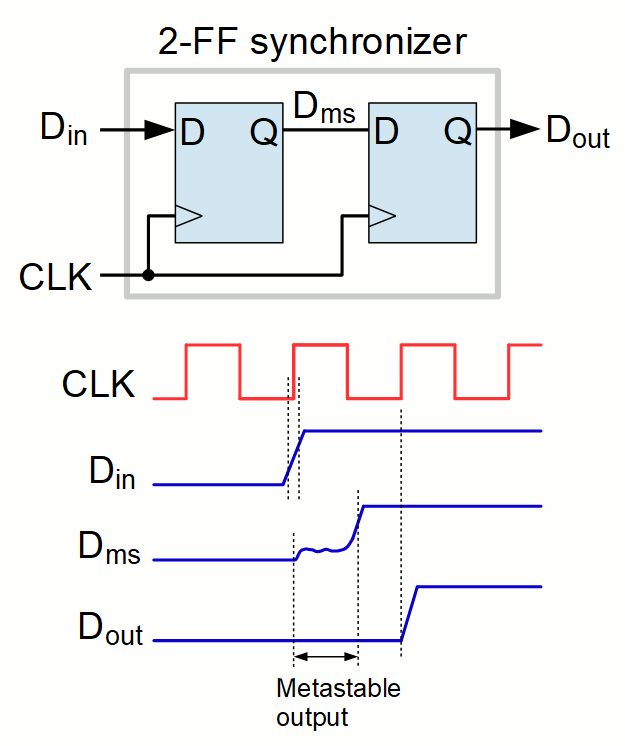
By Lambtron - Own work, CC BY-SA 4.0, https://commons.wikimedia.org/w/index.php?curid=86059204