|
|
||
|---|---|---|
| .citd | ||
| .main-meta | ||
| avr128db48-using-crystal-osc-as-clock-for-rtc-in-sleep-mplab.X | ||
| images | ||
| .gitignore | ||
| LICENSE.txt | ||
| README.md | ||
README.md

Configure the External 32.768 kHz Crystal as an RTC Clock Source in Sleep Mode Using AVR128DB48
This code example demonstrates how to configure an external 32.768 kHz crystal as a clock source to the Real-Time Counter (RTC) module of AVR microcontrollers. In this code example, the RTC module of AVR128DB48 microcontroller is supplied with an external 32.768 kHz crystal clock source while the microcontroller is in Sleep mode (Power-Down mode). It will show the power consumption by the device in Sleep mode and how external crystal as clock is accurate and consumes less power than the internal high frequency (HF) oscillator.
Introduction
In many applications which are battery operated, the microcontroller is dependent on methodical Sleep mode techniques that shut down some or all peripheral operations to reduce the power consumption, enabling it to work for a longer time on limited resources. The AVR128DB48 microcontrollers of the AVR® DB family of microcontrollers family uses the latest technologies from Microchip with a flexible and low power architecture. The AVR128DB48 simplified set of features includes Real-Time Counter (RTC), which offers two timing functionalities in form of RTC and Periodic Interrupt Timer (PIT). The PIT functionality uses the same clock source as RTC, but it can be enabled independently. The objective of this example is to show how to use RTC in Sleep mode (Power-Down mode) with an external crystal as a clock source.
Useful Links
Description
The objective of this code example is to enable low-power "Power-Down" mode in the microcontroller and configure the RTC module to operate in PIT mode using an external 32.768 kHz crystal oscillator, and completely shut down the microcontroller system clock and peripherals. Thereby, the microcontroller wakes up from Sleep to PIT interrupt. This implementation helps to minimize the microcontroller average power consumption. For the demonstration purpose, the switch event is used to switch to the external crystal oscillator as the clock source and lets the microcontroller enter Sleep mode. After the RTC period elapse, the PIT interrupt occurs and the clock source for the microcontroller switches back to the internal HF oscillator and is in Active mode.
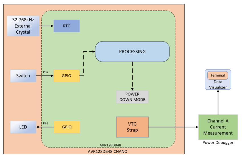
Figure 1: System Block Diagram
Software Tools
MPLAB® X IDE compiler and graphical code generators are used throughout the application firmware development. Below are the tools used for the demo application:
- MPLAB X IDE v6.05.0 or newer
- XC8 Compiler v2.40.0 or newer
- MPLAB Data Visualizer v1.3.1160
- Microchip AVR-Dx_DFP Series Device Support Pack 2.3.272 or newer
- MPLAB Code Configurator v5.2.2 or newer
- RTC 4.2.4
- SLPCTRL 3.0.4
Note: For running the demo, the installed tool versions should be the same or newer. This example is not tested with the previous versions.
Hardware Tools
Application Firmware
The example firmware uses the RTC peripheral to showcase the working of a microcontroller in Sleep mode by using 32.768 kHz external crystal oscillator as its clock source. During the active period, the system uses the 4 MHz internal oscillator. The Sleep control system peripheral is configured in Power-Down mode with the Performance mode being set to auto. Here, in Power-Down Sleep mode, only the Periodic Interrupt Timer functionality is available. The PIT uses the same clock source as RTC. The PIT interrupt period is configured for 30s. If a switch press event is detected, the PIT functionality gets enabled, and the microcontroller enters the Power-Down mode. After the period of 30s is completed, the PIT generates an interrupt to wake up the device from Sleep. The PI flag is monitored via the Interrupt Service Routine (ISR) to see if the PIT period is elapsed. As soon as it wakes up, the PIT functionality gets disabled and the MCU continues to stay in Active mode until a new switch press event is detected.
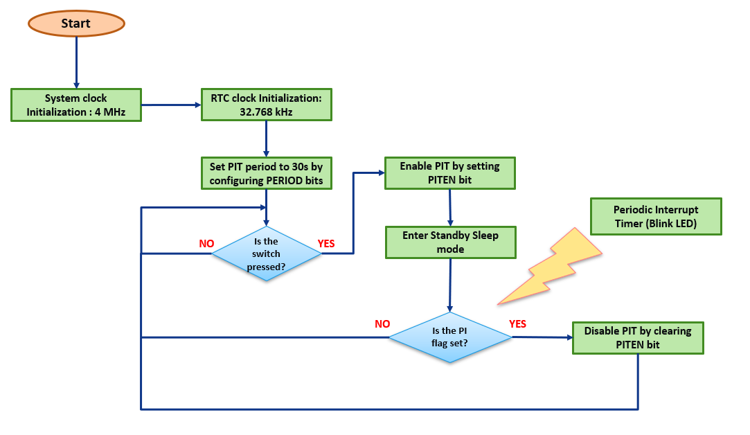
Figure 2: Application Firmware Flowchart
Demo Operation
- Make the hardware connections as shown in the hardware setup. Power up the Curiosity Nano board using a micro-USB cable.
- Download the firmware available from the GitHub code example page.
- Build the project using latest version of tools as mentioned in the Software Tools section and flash the generated file on the AVR128DB48 microcontroller.
- Observe the device current consumption on the Data Visualizer Window in the Active mode.
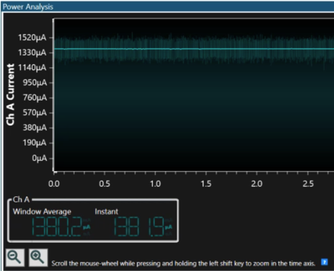
Figure 3: Active Current
- Press the on-board switch. It will switch the clock source to the external crystal.
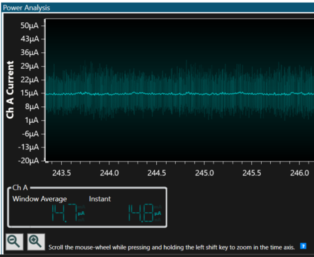
Figure 4: Sleep Current
- Observe the device current consumption in the Sleep mode.
- Wait for 30s or any further switch press to determine the current consumption in Active mode.
Conclusion
The power consumption of the microcontroller plays an important role in the battery powered applications. Hence, it is important to keep the microcontroller power consumption as minimum as possible for a longer battery life. This code example demonstrates low-power Sleep implementation using RTC and external crystal oscillator of AVR128DB48 microcontroller, as the external crystal oscillator provides a better overall performance compared to the internal oscillator and also minimizes the overall power consumptions of the microcontroller.
Appendix
MPLAB Code Configurator (MCC) is a graphical programming environment that generates seamless, easy to understand C code that gives a head start to the project. It saves the designer’s time to initialize and configure all the modules, and to go through the data sheets. Using an instructive interface, it enables and configures all peripherals and functions specific to the application requirements.
Start by creating a new Project and open MCC
- Open MPLAB X IDE
- Go to File>New Project
- Select Microchip Embedded>Standalone Project
- Enter the device name. In this case, select AVR128DB48 device
- Name the project
- Launch MCC tool by navigating to Tools>Embedded>MPLAB Code Configurator v4: Open/Close. Alternatively, click the MCC icon to launch the MCC tool
System configuration
System Clock
Open Clock Control setup present under System dropdown menu in Project Resources tab
- Clock Selection: Internal high frequency Osc
- Internal Osc. Freq.: 1-32 MHz internal Osc
- Enable System Clock Out
- Enable Run Standby 32.768 kHz crystal oscillator
- Enable Low Power Mode
The following figure shows the system configuration setting in MCC tool.
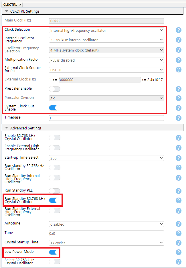
Figure 5: System Configuration
SLPCTRL
Open SLPCTRL setup present under System dropdown menu in Project Resources tab
- Enable Sleep
- Sleep Mode: PDOWN
- Performance Mode: AUTO
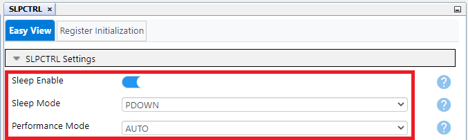
Figure 6: Sleep Control Configuration
RTC
Open RTC setup present under Driver dropdown menu in Project Resources tab
- Enable RTC
- RTC Clock Source: 32.768 kHz from XOSC32K
- Pre-scaling Factor: RTC Clock/32768
- Compare(s): 30
- Enable Compare Match Interrupt
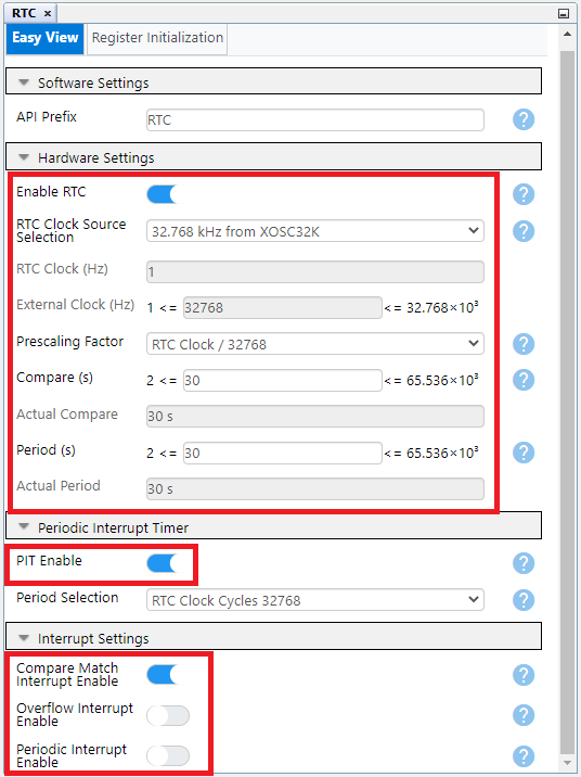
Figure 7: RTC Configuration
Pin Mapping
The following images informs about the pin usage in the project.
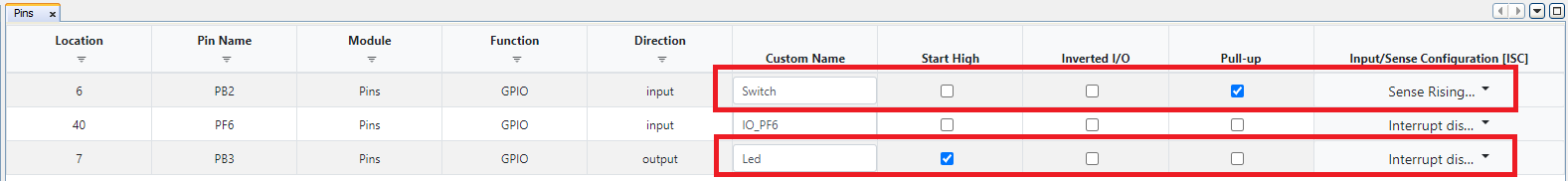
Figure 8: Pin Mapping (List View)
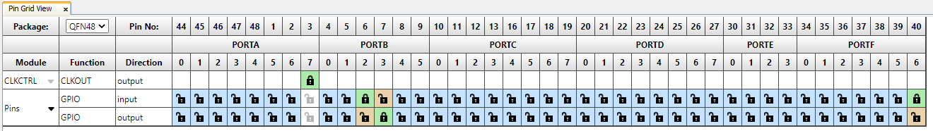
Figure 9: Pin Mapping (Navigation View)
Hardware Setup
The following figure consists of AVR128DB48 Curiosity Nano Evaluation kit along with a Power Debugger. Connect the Power Debugger to the MCU using connecting cables.
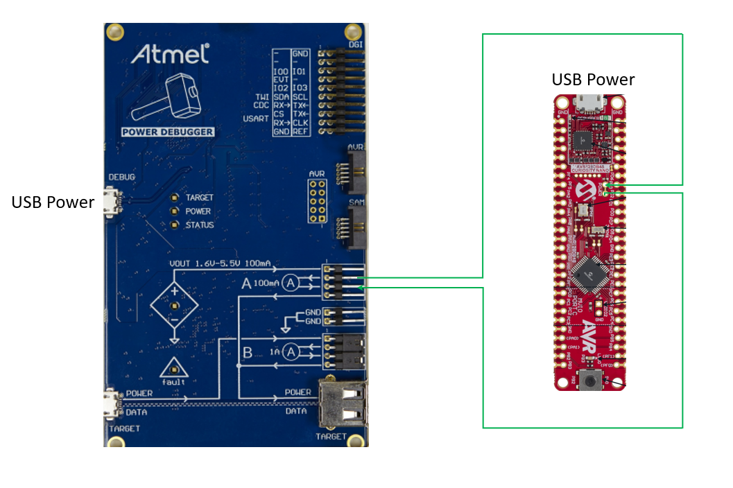
Figure 10: Hardware Setup
Data Visualizer
- The Data Gateway Interface (DGI) is available on the Microchip evaluation kits with an embedded programmer and debugger (EDBG) . These evaluation kits can communicate with the data visualizer through DGI. The figure below shows the DGI control panel of the data visualizer. All detected DGI devices are listed in the dropdown list with the kit name and serial number. Using the Connect button will connect to the selected DGI device and query for available interfaces.
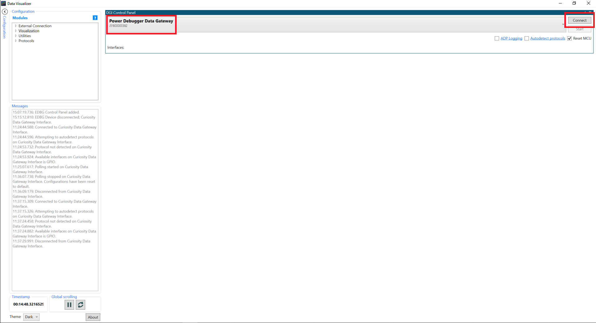
Figure 11: DGI Window
- The available interfaces will be listed under Interfaces. To enable one, check the box next to the name. When it is enabled, the sources and sinks can be connected to other endpoints. The Gear button is used to configure the interface. See the interface-specific sections for an explanation of the configuration fields. In this case, Power.
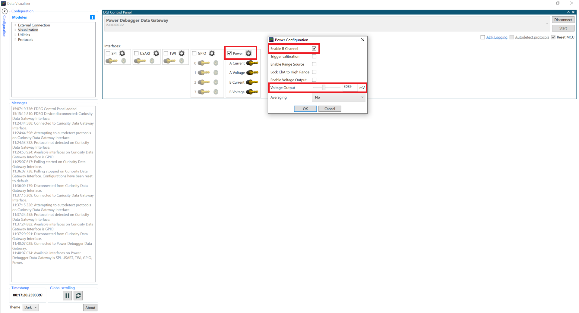
Figure 12: Interfaces and Settings
- To start polling data from the interfaces, click the Start button. The Reset MCU check box will cause the MCU to be held in Reset during start. The Power Analysis module is made specifically for analyzing power consumption over time.
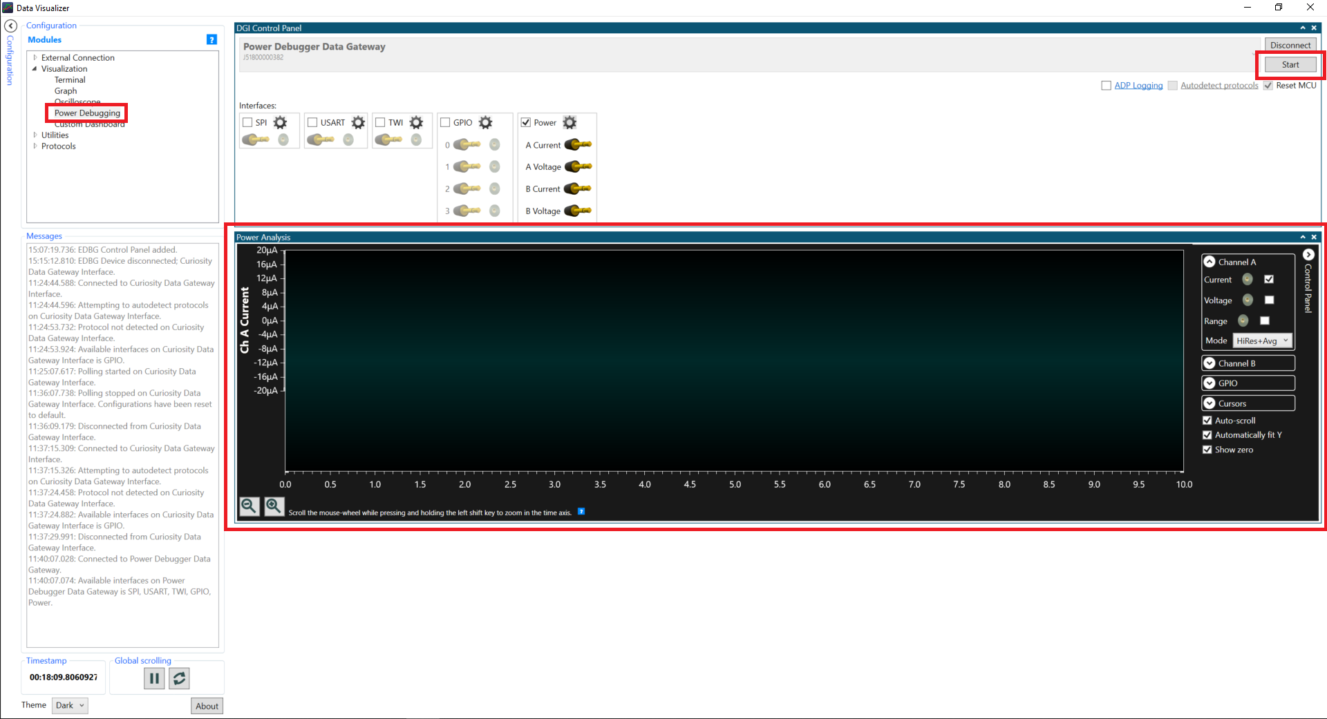
Figure 13: Power Analysis Window
- Drag the Channel A Current and Channel A Voltage pins to their respective power analysis window, and then measure the current consumption of the microcontroller.
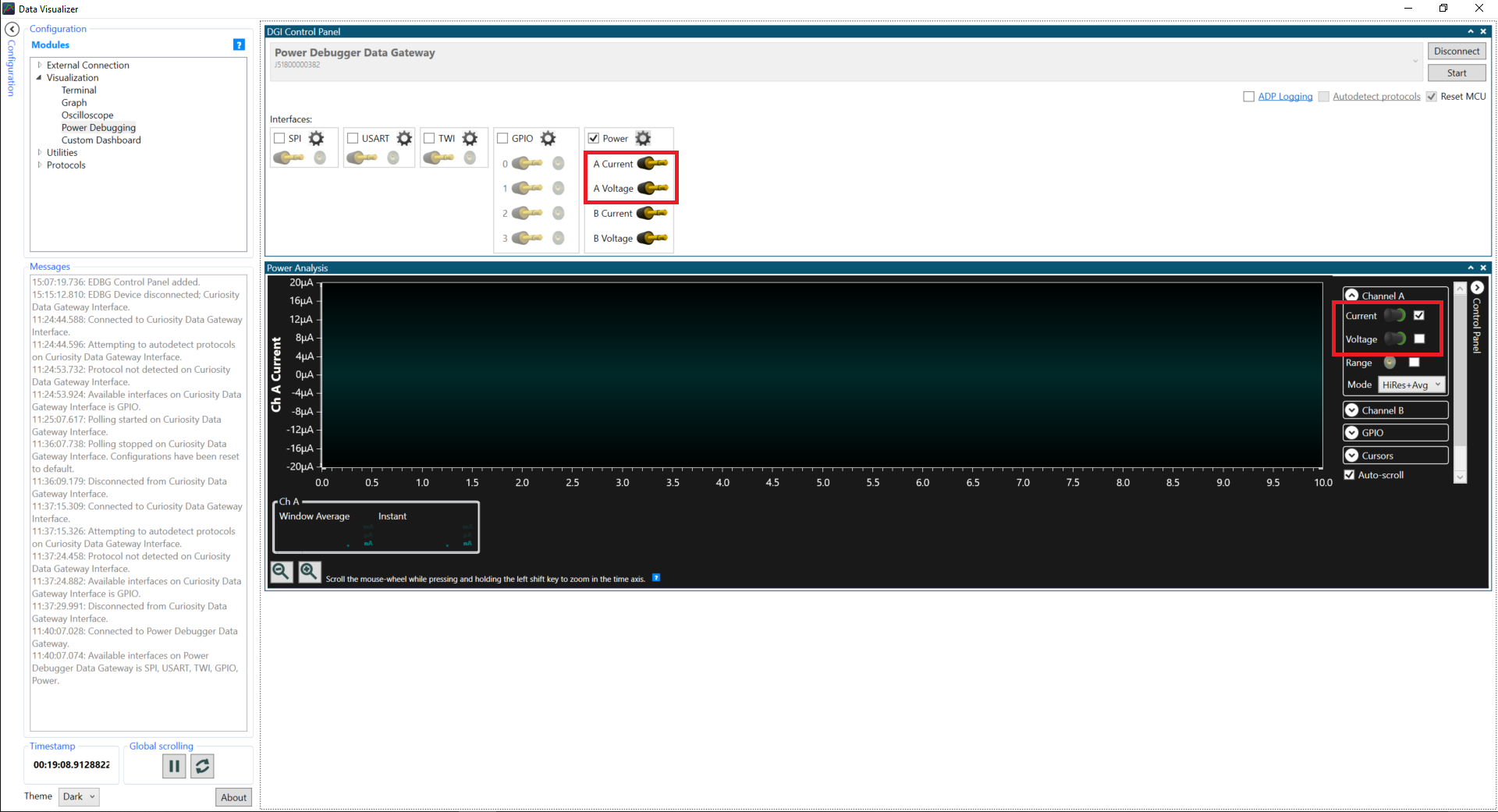
Figure 14: Power Analysis Channel Settings