|
|
||
|---|---|---|
| .citd | ||
| .main-meta | ||
| avr128da48-cnano-adc-temperature-measurement-mplab.X | ||
| images | ||
| .gitignore | ||
| README.md | ||
README.md

Analog-to-Digital Converter (ADC) - Temperature Measurement Using AVR128DA48 Microcontroller
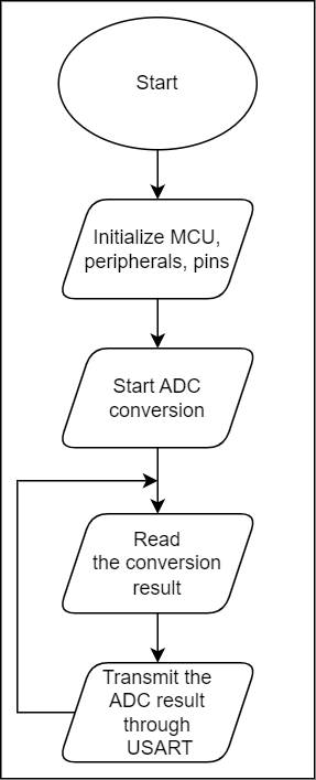
In this application, the ADC will be used to measure the temperature using the on-board specific sensor, and the results will be transmitted through Universal Synchronous and Asynchronous Receiver and Transmitter (USART). The software's example code diagram is presented in the figure below.
Related Documentation
More details and code examples on the AVR128DA48 can be found at the following links:
- AVR128DA48 Product Page
- AVR128DA48 Code Examples on GitHub
- Using 12-Bit ADC for Conversions, Accumulation, and Triggering Events
Software Used
- MPLAB® X IDE v6.15 or newer
- MPLAB® XC8 v2.45 or newer
- AVR-Dx Series Device Pack v2.3.272 or newer
- MPLAB® Data Visualizer
Hardware Used
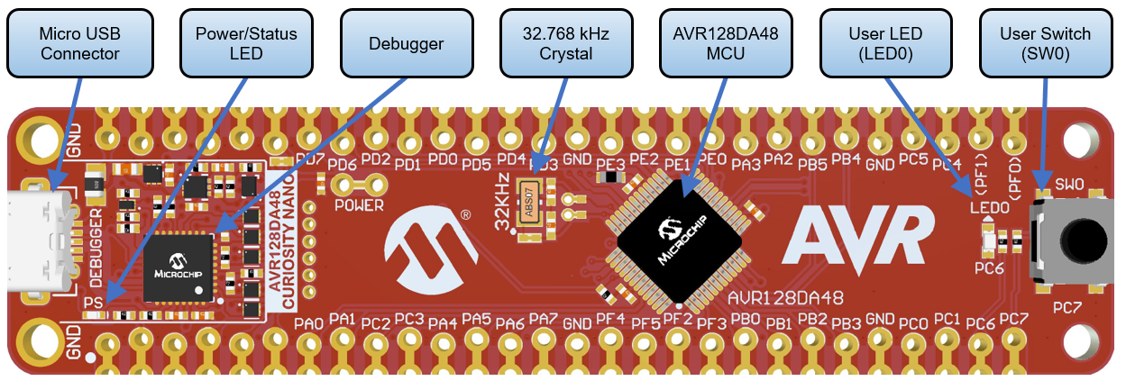
- AVR128DA48 Curiosity Nano Development board is used as a test platform.
Operation
To program the Curiosity Nano board with this MPLAB X project, follow the steps provided in the How to Program the Curiosity Nano Board chapter.
Setup
As an input of the ADC, the internal temperature sensor is used for measurements.
The following pin configuration must be made for this project:
| Pin | Configuration |
|---|---|
| PC0 (TX) | Digital Output |
Demo
After alternatively cooling and warming up the microcontroller, the converted sensor's temperature from the ADC result will be plotted on the graph from Data Visualizer plugin, as in picture below. Follow the steps in the How to Use the MPLAB Data Visualizer section to set up the Data Visualizer, so that it can accurately view the plotted values through USART.
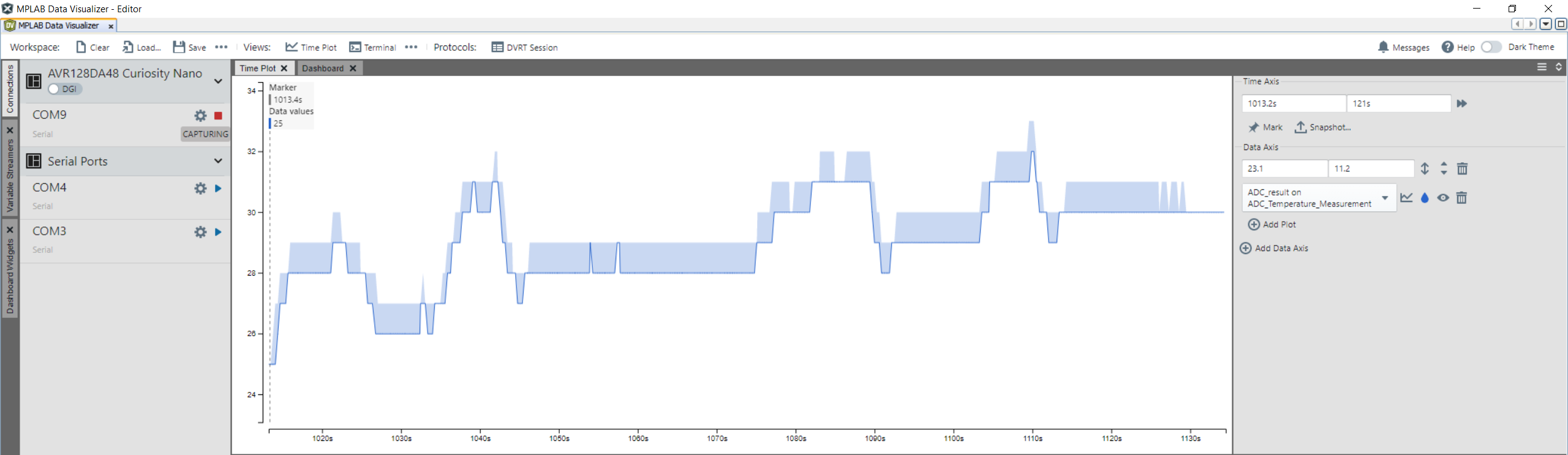
Note: The plotted variable called ADC_result on the Data Visualiser plugin must be configured as int16 type.
Summary
This application showcases how the AVR-DA devices measure the temperature using the ADC.
How to Use the MPLAB Data Visualizer
This section illustrates how to use the MPLAB X Data Visualizer to send commands and receive information, but prior to programming the AVR128DA48 Curiosity Nano Board. This can be applied to any other projects.
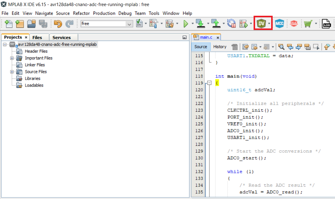
- Open the software terminal in MPLAB X IDE. Click on the Data Visualizer button.
- Prepare the settings in Data Visualizer.
- Click on the specific serial port communication COMx
- Set the correct Baud Rate
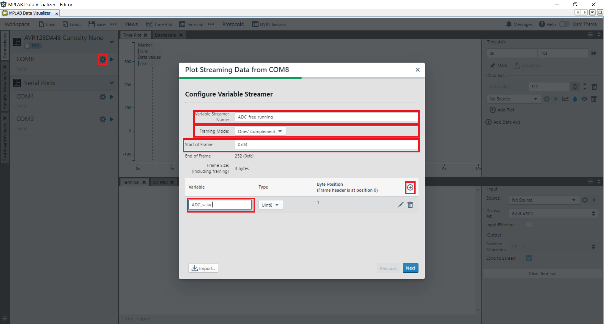
- In the Connections tab, at the COMx option, press New variable streamer...
- Type a specific Variable Streamer Name
- Choose Ones' Complement from the Framing Mode dropdown menu
- Type a specific value from the Start of Frame, press Add a variable
- Type a specific name for the variable name in Variable Name
- Press Next, after that press Next again
- Optional: Save these settings as a json file by pressing Save as
- See the expected result on Data Visualizer.
- Select Source from Time Plot window
- Click Start Streaming COMx the communication serial port
- Click Scroll axis automatically.

How to Program the Curiosity Nano board
This chapter shows how to use the MPLAB X IDE to program an AVR® device with an Example_Project.X. This can be applied for any other projects.
-
Connect the board to the PC.
-
Open the Example_Project.X project in MPLAB X IDE.
-
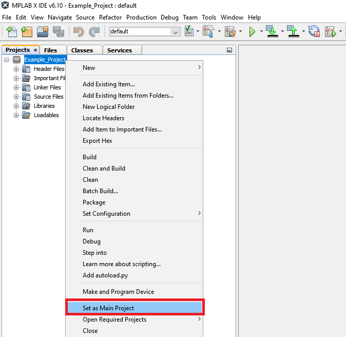
Set the Example_Project.X project as main project.
- Right click on the project in the Projects tab and click Set as Main Project.
- Right click on the project in the Projects tab and click Set as Main Project.
-
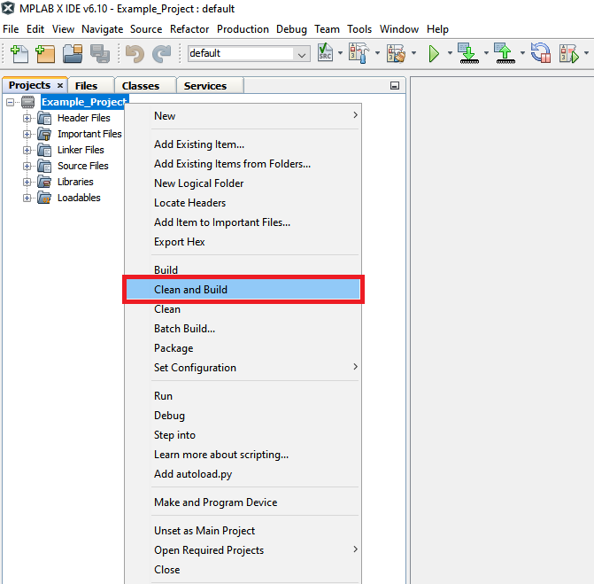
Clean and build the Example_Project.X project.
- Right click on the Example_Project.X project and select Clean and Build.
- Right click on the Example_Project.X project and select Clean and Build.
-
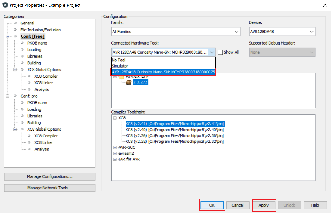
Select the AVRxxxxx Curiosity Nano in the Connected Hardware Tool section of the project settings:
- Right click on the project and click Properties
- Click on the arrow under the Connected Hardware Tool
- Select the AVRxxxxx Curiosity Nano (click on the SN), click Apply and then click OK:
-
Program the project to the board.
- Right click on the project and click Make and Program Device.
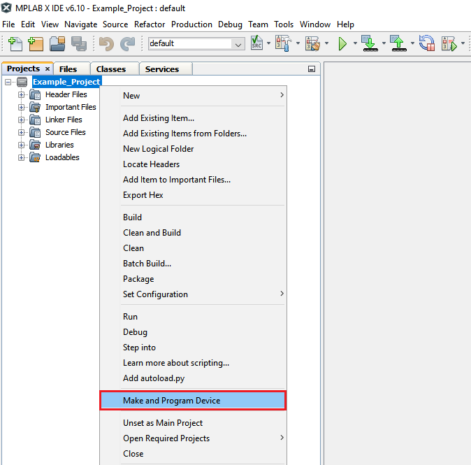
- Right click on the project and click Make and Program Device.