|
|
||
|---|---|---|
| .. | ||
| CMakeLists.txt | ||
| limesdrinput.cpp | ||
| limesdrinput.h | ||
| limesdrinput.pro | ||
| limesdrinputgui.cpp | ||
| limesdrinputgui.h | ||
| limesdrinputgui.ui | ||
| limesdrinputplugin.cpp | ||
| limesdrinputplugin.h | ||
| limesdrinputsettings.cpp | ||
| limesdrinputsettings.h | ||
| limesdrinputthread.cpp | ||
| limesdrinputthread.h | ||
| readme.md | ||
readme.md
LimeSDR input plugin
Introduction
This input sample source plugin gets its samples from a LimeSDR device.
☞ LimeSuite 19.01.0 is used in the binary builds and the Docker image. You have to make sure the corresponding gateware version is loaded in the LimeSDR. Check LimeSDR documentation for information about gateware.
⚠ LimeSDR-Mini seems to have problems with Zadig driver therefore this plugin will work in Linux only.
LimeSDR is a 2x2 MIMO device so it has two receiving channels that can run concurrently. To activate the second channel when the first is already active just open a new source tab in the main window (Devices -> Add source device) and select the same LimeSDR device.
Interface

1: Common stream parameters

1.1: Frequency
This is the center frequency of reception in kHz.
1.2: Start/Stop
Device start / stop button.
- Blue triangle icon: device is ready and can be started
- Green square icon: device is running and can be stopped
- Magenta (or pink) square icon: an error occurred. In the case the device was accidentally disconnected you may click on the icon to stop, plug back in, check the source on the sampling devices control panel and start again.
1.3: Record
Record baseband I/Q stream toggle button
1.4: ADC sample rate
This is the sample rate at which the ADC runs in kS/s (k) or MS/s (M) before hardware decimation (8). Thus this is the device to host sample rate (5) multiplied by the hardware decimation factor (3).
☞ Note that changing the hardware decimation factor (3) or the device to host sample rate (5) may change the DAC clock sample rate and therefore the Tx side hardware interpolation factor and/or host to device sample rate.
1.5: Stream sample rate
In device to host sample rate input mode (5) this is the baseband I/Q sample rate in kS/s. This is the device to host sample rate (6) divided by the software decimation factor (4).
In baseband sample rate input mode (5) this is the device to host sample rate in kS/s. This is the baseband sample rate (8) multiplied by the software decimation factor (4)
1.6: Channel number
LimeSDR is a 2x2 MIMO device so it has two receiving channels. This shows the corresponding Rx channel index (0 or 1).
2: NCO, DC/IQ correction and external clock controls

2.1: NCO toggle
The button is lit when NCO is active and dark when inactive.
Use this button to activate/deactivate the TSP NCO. The LMS7002M chip has an independent NCO in each Rx channel that can span the bandwidth received by the ADC. This effectively allows non zero digital IF.
2.2: NCO frequency shift
This is the frequency shift applied when the NCO is engaged thus the actual LO frequency is the center frequency of reception minus this value. Use the thumbwheels to adjust frequency as done with the LO (1.1). Pressing shift simultaneously moves digit by 5 and pressing control moves it by 2. The boundaries are dynamically calculated from the LO center frequency, sample rate and hardware decimation factor.
☞ Engaging the NCO shifts the center frequency of reception by the shift amount. You have to retune the center frequency (1.1) to get back to the frequency before the NCO was engaged. You may also select the NCO frequency and then tune the center frequency.
☞ In the LMS7002M TSP block the NCO sits before the decimator (see Fig.14 of the datasheet p.7) so it runs at the actual ADC rate. Hence the NCO limits are calculated as +/- half the device to host sample rate multiplied by the hardware decimation factor. For example with a 4 MS/s device to host sample rate (5) and a hardware decimation of 16 (3) you have +/- 32 MHz span around the LO for the NCO. In this example you can tune all HF frequencies with the center frequency set at its lowest (30 MHz).
2.3: DC component auto correction
Enables or disables the auto remove DC component
2.4: I/Q balance auto correction
Enables or disables the auto I/Q balance correction. The DC correction must be enabled for this to be effective.
2.5: External clock control
Use this button to open a dialog that lets you choose the external clock frequency and enable or disable it. When disabled the internal 30.72 MHz VCTCXO is used.

2.5.1: External clock frequency
Can be varied from 5 to 300 MHz
Use the thumbwheels to adjust frequency as done with the LO (1.1). Pressing shift simultaneously moves digit by 5 and pressing control moves it by 2. The boundaries are dynamically calculated from the LO center frequency, sample rate and hardware decimation factor.
2.5.2: Enable/disable external clock input
Use this checkbox to enable or disable the external clock input
2.5.3: Confirm changes
Use the "OK" button to confirm your changes
2.5.4: Dismiss changes
Use the "Cancel" button to dismiss your changes
3: LMS7002M hardware decimation factor
The TSP block in the LMS7002M hardware has a decimation chain that acts on both Rx channels. It is composed of 5 halfband decimation stages and therefore can achieve decimation between 1 (no decimation) and 32 in increasing powers of 2: 1, 2, 4, 8, 16, 32.
Thus the actual sample rate of the ADC is the stream sample rate (5) multiplied by this factor.
4: Software decimation factor
The I/Q stream from the LimeSDR is downsampled by a power of two by software inside the plugin before being sent to the passband. Possible values are increasing powers of two: 1 (no decimation), 2, 4, 8, 16, 32.
5: Device to host sample rate / Baseband sample rate input toggle
Use this toggle button to switch the sample rate input next (8) between device to host sample rate and baseband sample rate input. The button shows the current mode:
- SR: device to host sample rate input mode. The baseband sample rate (1.5) is the device to host sample rate (6) divided by the software decimation factor (4).
- BB: baseband sample rate input mode. The device to host sample rate (1.5) is the baseband sample rate (8) multiplied by the software decimation factor (4).
6: Sample rate
This is the LMS7002M device to/from host stream sample rate or baseband sample rate in samples per second (S/s). The control (5) is used to switch between the two input modes. The device to/from host stream sample rate is the same for the Rx and Tx systems.
The limits are adjusted automatically. In baseband input mode the limits are driven by the decimation factor (4). You may need to increase this decimation factor to be able to reach lower values.
Use the wheels to adjust the sample rate. Pressing shift simultaneously moves digit by 5 and pressing control moves it by 2. Left click on a digit sets the cursor position at this digit. Right click on a digit sets all digits on the right to zero. This effectively floors value at the digit position. Wheels are moved with the mousewheel while pointing at the wheel or by selecting the wheel with the left mouse click and using the keyboard arrows.
The LMS7002M uses the same clock for both the ADCs and DACs therefore this sample rate affects all of the 2x2 MIMO channels.
7: Filters and transverter mode
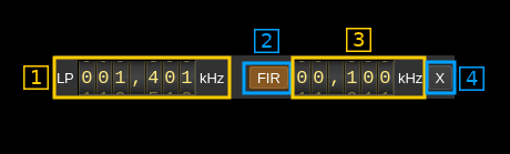
7.1: Rx hardware filter bandwidth
This is the Rx hardware filter bandwidth in kHz in the LMS7002M device for the given channel. Boundaries are updated automatically but generally are from 1.4 to 130 MHz in 1 kHz steps. Use the wheels to adjust the value. Pressing shift simultaneously moves digit by 5 and pressing control moves it by 2.
7.2: TSP FIR filter toggle
The TSP in the LMS7002M chip has a FIR filter chain per channel. Use this button to activate or deactivate the TSP FIR filter.
7.3: TSP FIR filter bandwidth
Use the wheels to adjust the bandwidth of the hardware TSP FIR filter. Pressing shift simultaneously moves digit by 5 and pressing control moves it by 2.
7.4: Transverter mode open dialog
This button opens a dialog to set the transverter mode frequency translation options:

Note that if you mouse over the button a tooltip appears that displays the translating frequency and if translation is enabled or disabled. When the frequency translation is enabled the button is lit.
7.4.1: Translating frequency
You can set the translating frequency in Hz with this dial. Use the wheels to adjust the sample rate. Left click on a digit sets the cursor position at this digit. Right click on a digit sets all digits on the right to zero. This effectively floors value at the digit position. Wheels are moved with the mousewheel while pointing at the wheel or by selecting the wheel with the left mouse click and using the keyboard arrows. Pressing shift simultaneously moves digit by 5 and pressing control moves it by 2.
The frequency set in the device is the frequency on the main dial (1) minus this frequency. Thus it is positive for down converters and negative for up converters.
For example a mixer at 120 MHz for HF operation you would set the value to -120,000,000 Hz so that if the main dial frequency is set at 7,130 kHz the PlutoSDR will be set to 127.130 MHz.
If you use a down converter to receive the 6 cm band narrowband center frequency of 5670 MHz at 432 MHz you would set the translating frequency to 5760 - 432 = 5328 MHz thus dial +5,328,000,000 Hz.
For bands even higher in the frequency spectrum the GHz digits are not really significant so you can have them set at 1 GHz. Thus to receive the 10368 MHz frequency at 432 MHz you would set the translating frequency to 1368 - 432 = 936 MHz. Note that in this case the frequency of the LO used in the mixer of the transverter is set at 9936 MHz.
The Hz precision allows a fine tuning of the transverter LO offset
7.4.2: Translating frequency enable/disable
Use this toggle button to activate or deactivate the frequency translation
7.4.3: Confirmation buttons
Use these buttons to confirm ("OK") or dismiss ("Cancel") your changes.
8: Gain settings

8.1: Gain mode
Use this combo to select either the automatic gain (Aut) or the manual (Man) gain setting. Automatic gain sets the global gain using a predefined table for LNA, TIA and PGA gain blocks. This global gain is set with button 9.2. When manual gain is engaged the LNA, TIA and PGA gains can be set independently with the 9.3, 9.4 and 9.5 buttons respectively.
Please refer to LMS7002M documentation for a precise description of LNA, TIA and PGA and their location in the Rx chain. To summarize these blocks are placed in this order from antenna to ADC.
8.2: Global automatic gain
Use this button to adjust the global gain of the LNA, TIA and PGA. LimeSuite software automatically set optimal values of the amplifiers to achieve this global gain. This gain can be set between 0 and 70 dB in 1 dB steps. The value in dB appears at the right of the button.
8.3: LNA manual gain
Use this button to adjust the gain of tha LNA when manual gain mode is set (8.1). Gain can be set between 1 and 30 dB in 1 dB steps. However the hardware has 3 dB steps for the lower gain values so increasing or decreasing by one step does not always produce a change. The value in dB appears at the right of the button.
8.4: TIA manual gain
Use this combo to select the TIA gain in dB when manual gain mode is set (8.1). Possible values are 1,2 and 3 dB.
8.5: PGA manual gain
Use this button to adjust the gain of tha PGA when manual gain mode is set (8.1). Gain can be set between 0 and 32 dB in 1 dB steps. The value in dB appears at the right of the button.
9: Antenna select
Use this combo box to select the antenna input:
- No: None
- Lo: Selects the low frequency input (700 to 900 MHz nominally)
- Hi: Selects the high frequency input (2 to 2.6 GHz)
- Wo: Selects the wideband input
- T1: Selects loopback from TX #1 (experimental)
- T1: Selects loopback from TX #2 (experimental)
10: Stream status indicator
This label turns green when status can be obtained from the current stream. Usually this means that the stream is up and running but not necessarily streaming data. The various status elements appear next on the same line (12)
11: Stream warning indicators
- U: turns red if stream experiences underruns
- O: turns red if stream experiences overruns
- P: turns red if stream experiences packet drop outs
12: Stream global (all Rx) throughput in MB/s
This is the stream throughput in MB/s and is usually about 3 times the sample rate for a single stream and 6 times for a dual Rx stream. This is due to the fact that 12 bits samples are used and although they are represented as 16 bit values only 12 bits travel on the USB link.
13: FIFO status
This is the fill percentage of the Rx FIFO in the LimeSuite interface. It should be zero most of the time.
14: Board temperature
This is the board temperature in degrees Celsius updated every ~5s. Before the first probe the display marks "00C" this is normal.
15: GPIO pins status
This is the hexadecimal representation of the 8 available GPIO pins of the on board LimeSDR GPIO header.