|
|
||
|---|---|---|
| .. | ||
| CMakeLists.txt | ||
| hackrfinput.cpp | ||
| hackrfinput.h | ||
| hackrfinput.pro | ||
| hackrfinputgui.cpp | ||
| hackrfinputgui.h | ||
| hackrfinputgui.ui | ||
| hackrfinputplugin.cpp | ||
| hackrfinputplugin.h | ||
| hackrfinputsettings.cpp | ||
| hackrfinputsettings.h | ||
| hackrfinputthread.cpp | ||
| hackrfinputthread.h | ||
| readme.md | ||
readme.md
HackRF input plugin
Introduction
This input sample source plugin gets its samples from a HackRF device.
Interface
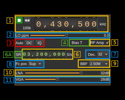
1: Common stream parameters
1.1: Frequency
This is the center frequency of reception in kHz.
1.2: Start/Stop
Device start / stop button.
- Blue triangle icon: device is ready and can be started
- Green square icon: device is running and can be stopped
- Red square icon: an error occurred. In the case the device was accidentally disconnected you may click on the icon, plug back in and start again.
If you have the Tx open in another tab and it is running then it will be stopped automatically before the Rx starts. In a similar manner the Rx will be stopped before the Tx is started from the Tx tab.
The settings on Rx or Tx tab are reapplied on start so these settings can be considered independent.
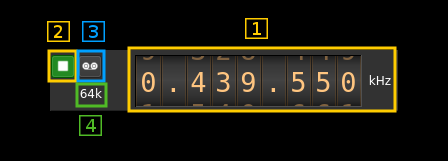
1.3: Record
Record baseband I/Q stream toggle button
1.4: Stream sample rate
In device to host sample rate input mode (6A) this is the baseband I/Q sample rate in kS/s. This is the device to host sample rate (6) divided by the decimation factor (7).
In baseband sample rate input mode (6A) this is the device to host sample rate in kS/s. This is the baseband sample rate (6) multiplied by the decimation factor (7)
2: Local Oscillator correction
Use this slider to adjust LO correction in ppm. It can be varied from -10.0 to 10.0 in 0.1 steps and is applied in software.
3: Auto correction options
These buttons control the local DSP auto correction options:
- DC: auto remove DC component
- IQ: auto make I/Q balance. The DC correction must be enabled for this to be effective.
4: Bias tee
Use this checkbox to toggle the +5V power supply on the antenna connector.
5:RF amp
Use this checkbox to toggle the extra low noise amplifier (LNA). This gives an additional gain of 14 dB.
6A: Device sample rate / Baseband sample rate input toggle
Use this toggle button to switch the sample rate input next (6) between device sample rate and baseband sample rate input. The button shows the current mode:
- SR: device sample rate input mode. The baseband sample rate (1.4) is the device sample rate (6) divided by the decimation factor (7).
- BB: baseband sample rate input mode. The device sample rate (1.4) is the baseband sample rate (6) multiplied by the decimation factor (7).
6: Sample rate
This is the HackRF device ADC sample rate or baseband sample rate in samples per second (S/s). The control (6A) is used to switch between the two input modes.
The limits are adjusted automatically. In baseband input mode the limits are driven by the decimation factor (7). You may need to increase this decimation factor to be able to reach lower values.
Use the wheels to adjust the sample rate. Left click on a digit sets the cursor position at this digit. Right click on a digit sets all digits on the right to zero. This effectively floors value at the digit position. Wheels are moved with the mousewheel while pointing at the wheel or by selecting the wheel with the left mouse click and using the keyboard arrows. Pressing shift simultaneously moves digit by 5 and pressing control moves it by 2.
7: Decimation factor
The device stream from the HackRF is decimated to obtain the baseband stream. Possible values are:
- 1: no decimation
- 2: divide device stream sample rate by 2
- 4: divide device stream sample rate by 4
- 8: divide device stream sample rate by 8
- 16: divide device stream sample rate by 16
- 32: divide device stream sample rate by 32
8: Baseband center frequency position relative the the HackRF Rx center frequency
- Cen: the decimation operation takes place around the HackRF Rx center frequency Fs
- Inf: the decimation operation takes place around Fs - Fc.
- Sup: the decimation operation takes place around Fs + Fc.
With SR as the sample rate before decimation Fc is calculated depending on the decimaton factor:
- 2: Fc = SR/4
- 4: Fc = 3*SR/8
- 8: Fc = 5*SR/16
- 16: Fc = 11*SR/32
- 32: Fc = 21*SR/64
- 64: Fc = 21*SR/128
9: Rx filter bandwidth
This is the Rx filter bandwidth in kHz. Possible values are: 1750, 2500, 3500, 5000, 5500, 6000, 7000, 8000, 9000, 10000, 12000, 14000, 15000, 20000, 24000, 28000 kHz.
10: Internal LNA gain
The LNA gain can be adjusted from 0 dB to 40 dB in 8 dB steps.
11: Rx variable gain amplifier gain
The Rx VGA gain can be adjusted from 0 dB to 62 dB in 2 dB steps.
Frequency synchronization with Tx
When a device set for the same physical device is present the device center frequencies are synchronized because there is only one LO for the physical device.
When the center frequency position Fc (control 8) is set to center (Cen) in both Rx and Tx the actual frequency of reception and transmission are the same.
In other cases for both frequencies to match you have to set the same sample rate and Fc position (either Inf or Sup) in the Rx and Tx.