Sync with master repository |
||
|---|---|---|
| Arduino-microfox | ||
| Docs | ||
| Hardware | ||
| LICENSE | ||
| README.md | ||
README.md
WB8WFK ARDF Foxoring Transmitter
This is a simple, inexpensive, transmitter and controller for conducting ARDF Foxoring competitions and for demonstrating ARDF principles. The software project is an Arduino script that builds for and runs on most Arduino-like products, including AdaFruit's Metro Mini 328, or SparkFun's Arduino Pro Mini 328, and most any board with an ATMEGA328P processor.
Controller support for all the common ARDF competition formats is provided: Classic, Sprint, and Foxoring.
Software
The software is a proper Arduino script that will open and build without warnings or errors in Arduino IDE version 1.8.12 and later. It has also been shown to work with the online Arduino Web Editor. The Arduino IDE can be used to program a device that contains a compatible bootloader. Most Arduino products ship with a bootloader pre-installed.
After being programmed, the controller can be configured via a serial port on the board. An Arduino board that includes a USB-to-Serial converter will allow you to configure the controller with a simple USB cable (standard to micro) connected between a USB port on your computer to one on the Arduino board. Less sophisticated Arduino boards lacking a USB-to-Serial converter will require a special FTDI cable like AdaFruit's FTDI Serial TTL-232 USB Cable, or SparkFun's FTDI Cable 5V.
The fox-controller software provides an output pin for controlling a transmitter for sending Morse code characters (high = key down; low = key up) and a separate pin that sends the Morse code as audio tones that can be used to drive a speaker. The controller can also provide a sequence of starting-tones prompting competitors to begin a competition, and can thus serve as an electronic starting "gun" for use in ARDF events.
Serial Commands
The fox-controller serial interface operates at 57600 baud, and can be accessed using any serial TTY interface program such as PuTTY or Arduino's own Serial Monitor tool. It provides a command prompt > indicating that it is ready to receive any of the following commands.
> CAL [num]  <= * Sets the clock calibration for precise timing

> CAL  <= Displays the clock calibration setting

> DIP [val]  <= * Sets the competition format, overriding the DIP switch settings

> DIP  <= Displays the competition format setting

> FAC  <= Sets saved EEPROM values to their original defaults

> GO  <= Starts operation from zero seconds, equivalent to pressing the sync button

> ID [string]  <= * Sets the callsign that gets sent

> ID  <= Displays the saved callsign setting

> LED [on|off]  <= * Turns on/off LED pin

> LED  <= Displays the LED pin setting

> RST  <= Resets the processor

> SPD ID [num]  <= * Sets the ID code speed in WPM

> SPD  <= Displays the ID code speed setting

> STA [on|off]  <= * Turns on/off the starting tones function

> STA  <= Displays the starting tones setting

> TEM  <= Displays the processor's temperature in C

> TXE [on|off]  <= * Turns on/off the transmitter

> TXE  <= Displays the transmitter setting

> VER  <= Displays the software version number
* These values get stored to EEPROM and are retained between power cycles.
Hardware
Look in the Hardware folder for all hardware-related documents
Pinout
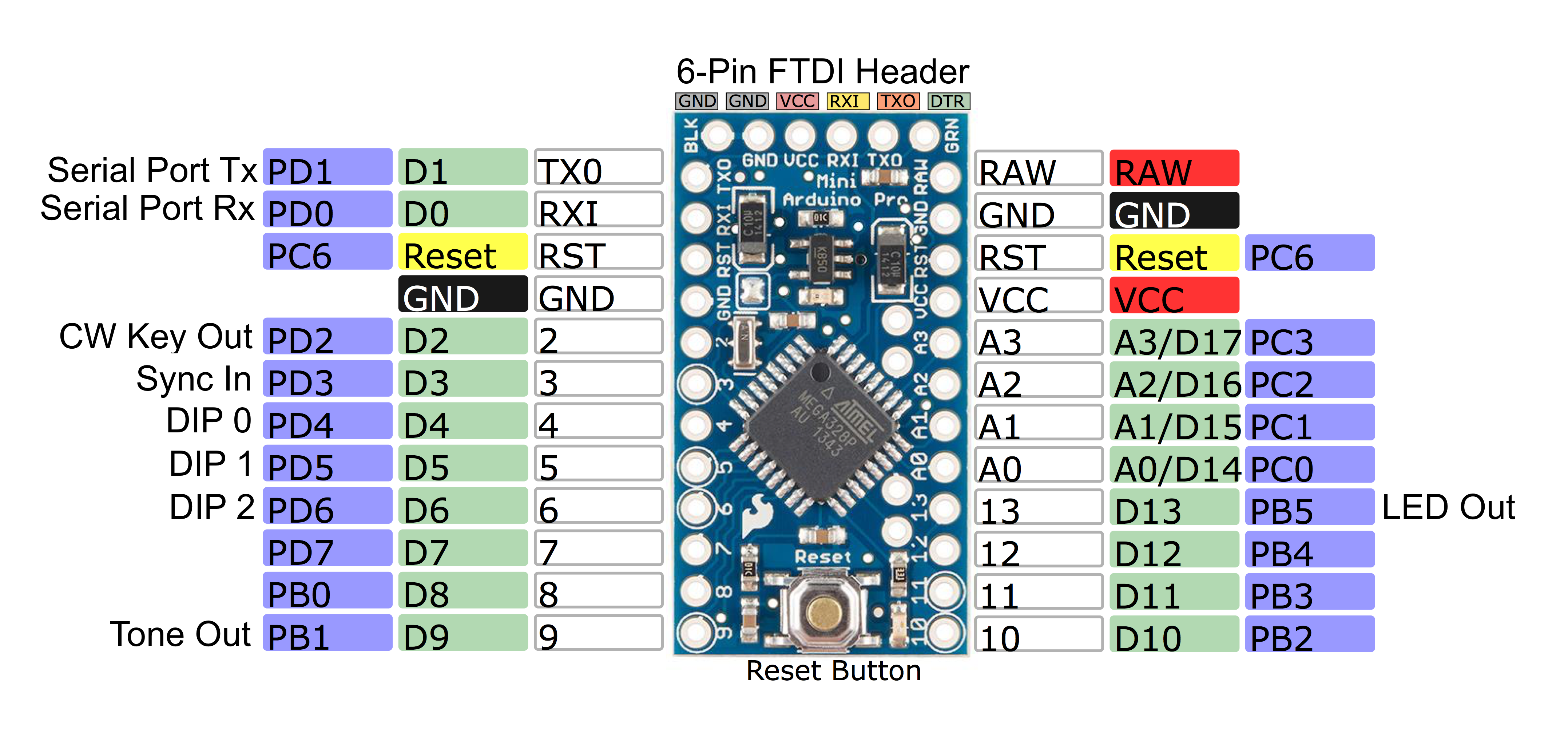
PB1 - Board Pin 9  (Output) <= Audio Out (=Gnd when no tone)

PB5 - Board Pin 13 (Output) <= LED On=VCC

PD2 - Board Pin 2  (Output) <= Key/PTT On=VCC

PD3 - Board Pin 3  (Input)  <= Synchronize (mom. switch to Gnd)

PD4 - Board Pin 4  (Input) <= DIP Switch Bit 0 (switch to Gnd)

PD5 - Board Pin 5  (Input) <= DIP Switch Bit 1 (switch to Gnd)

PD6 - Board Pin 6  (Input) <= DIP Switch Bit 2 (switch to Gnd)
Usage
The transmitter can be configured using the serial port, or using the DIP switch and sync-button hardware interface. Only a subset of the possible configurations is available when using only the hardware interface. Configuring the DIP setting with a serial port command to anything but CLASSIC BEACON (zero) will disable the hardware DIP switch.
In the table below, default settings are shown in boldface. Serial command arguments may be abbreviated using the first letter of the word. For example: > DIP CLASSIC BEACON can be shortened to > DIP C B.
| Function | Software Commands | Hardware Settings |
|---|---|---|
| Homing Beacon | > DIP CLASSIC BEACON [Note: the DIP switch must also be set to 0-0-0] |
DIP = 0-0-0 |
| Classic Fox#1 | > DIP CLASSIC 1 > GO |
DIP = 0-0-1 Sync to start |
| Classic Fox#2 | > DIP CLASSIC 2 > GO |
DIP = 0-1-0 Sync to start |
| Classic Fox#3 | > DIP CLASSIC 3 > GO |
DIP = 0-1-1 Sync to start |
| Classic Fox#4 | > DIP CLASSIC 4 > GO |
DIP = 1-0-0 Sync to start |
| Classic Fox#5 | > DIP CLASSIC 5 > GO |
DIP = 1-0-1 Sync to start |
| Classic Demonstration | > DIP CLASSIC DEMO | DIP = 1-1-0 |
| Foxoring | > DIP FOXORING | DIP = 1-1-1 |
| Spectator Beacon | > DIP FOXORING SPEC | N/A |
| Sprint Fox Slow #1 | > DIP SPRINT S1 | N/A |
| Sprint Fox Slow #2 | > DIP SPRINT S2 | N/A |
| Sprint Fox Slow #3 | > DIP SPRINT S3 | N/A |
| Sprint Fox Slow #4 | > DIP SPRINT S4 | N/A |
| Sprint Fox Slow #5 | > DIP SPRINT S5 | N/A |
| Sprint Fox Fast #1 | > DIP SPRINT F1 | N/A |
| Sprint Fox Fast #2 | > DIP SPRINT F2 | N/A |
| Sprint Fox Fast #3 | > DIP SPRINT F3 | N/A |
| Sprint Fox Fast #4 | > DIP SPRINT F4 | N/A |
| Sprint Fox Fast #5 | > DIP SPRINT F5 | N/A |
| Sprint Demonstration | > DIP SPRINT DEMO | N/A |
| Starting Tones Generator | > DIP [any of the above] > STA ON > GO |
N/A |
| Synchronize | > GO | Pull sync pin low for at least 1 second Allow sync pin to rise [Must happen within 1 fox cycle after power-on] |