|
|
||
|---|---|---|
| 3D_Print_Housing | ||
| ATU_100_EXT_board | ||
| ATU_100_mini_board | ||
| README.md | ||
README.md
The latest firmware version is 3.2
New in the version 3.2
- Fixed bug with continuous data transfer to the display.
- Added new feature to disable all relays along with the timer display. New cell 35(33 for mini board) - 01 to activate the relay off function. Display Off Timer setup - cell 32 (30 for mini board). You can use this feature in your QRP setup where power consumption is critical.
- Timeout for display reset increased to 2 seconds. This is required for some OLED displays with a very long RC chain on the reset pin.
New in the version 3.1
The fider loss value now is zero by default, the tuner board shows mismatch loss only. To install your actual fider loss, power on the board with pushed TUNE button, use BYP and AUTO buttons to set needed value. The value will be saved immediatelly in the long-term memory (0x34 cell for extended board or 0x32 cell for mini boards).
Some errors were fixed.
Overload indication is fixed. It works when the input power exceeds the board possibility to meassure correct power.
How to rebuild a 100 Watt board to reliable work with QRP 1 - 5 Watt power, by ik3ssg (VIDEO)
New in the version 3.0
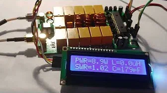
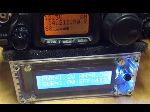
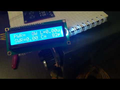
Added the ability to turn off the display backlight by timer and indication of the power delivered to the antenna and the transmitter efficiency. These sells were added in 3.0 firmware for EXT board :
31 - cell for setting a ratio of turns of the tandem match on which depends the upper limit of the measured power. The default value is 10, which corresponds to a maximum measured power of about 150 watts. To be able to measure power up to 1500 watts, you should use the high power indication mode and a tandem match with a ratio of 1 to 32. If the power does not exceed 40 watts, it makes sense to use a tandem-match with a ratio of 1: 5 turns, which will allow to work better with a minimum power of 1-5 watts. For other power values, the ratio of turns should be calculated so that the voltage at the measuring inputs of the microprocessor at maximum power does not exceed 4.096 Volts for the PIC16F1938 processor and 5.0 Volts for the PIC18F2520 processor.
32 – sell for setting the time of glow dysplay or its backlite, in seconds . The backlite is glowing whilw press any buttons and if RF power comes to input.П By default it is disabled, value 00.
33 — cell for setting of an addidional indication mode, value 00 — for indicating L and C only. Value 01 — for indicating the power delivered to the antenna and efficiency of fider and transmitter пwhen input power is enough for correct SWR meassuring. By default is enable, value 01.
Warning!!! The device does not take into account its own efficiency.
34 — cell for setting a feeder power loss ratio, the first number — integer part of decibell, second number — ten’s parts of decibell. Velue by default — 1.2 (12 writen in the cell). this value uses for counting the power delivered to antenna. The loss value can be found in the reference data for the used cable or you can measure the exact value yourself. If it is not necessary to take into account feeder losses, the value 00 should be written into the cell, then the calculations will correspond only to the mismatch losses.
For mini board : 0A - cell for setting a ratio of turns of the tandem match on which depends the upper limit of the measured power . The default value is 10, which corresponds to a maximum measured power of about 150 watts. If the power does not exceed 40 watts, it makes sense to use a tandem-match with a ratio of 1:5 turns, which will allow to work better with a minimum power of 1 -5 watts. For other power values, the ratio of turns should be calculated so that the voltage at the measuring inputs of the microprocessor at maximum power does not exceed 4.096 Volts for the PIC16F1938 processor and 5.0 Volts for the PIC18F2520 processor.
N7DDC ATU-100 mini board
The easy DIY 5x5 elements 100 Watt automatic antenna tuner
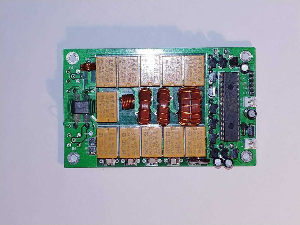
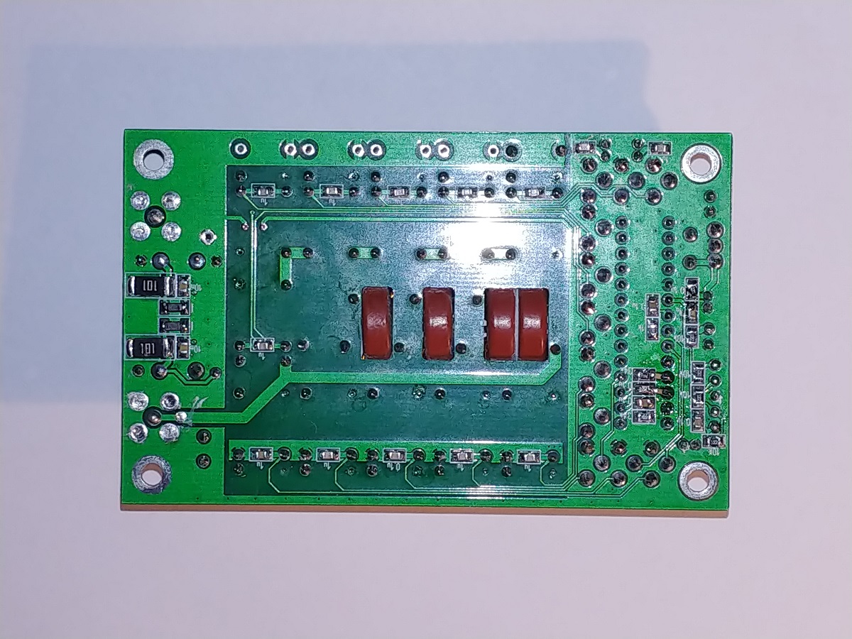
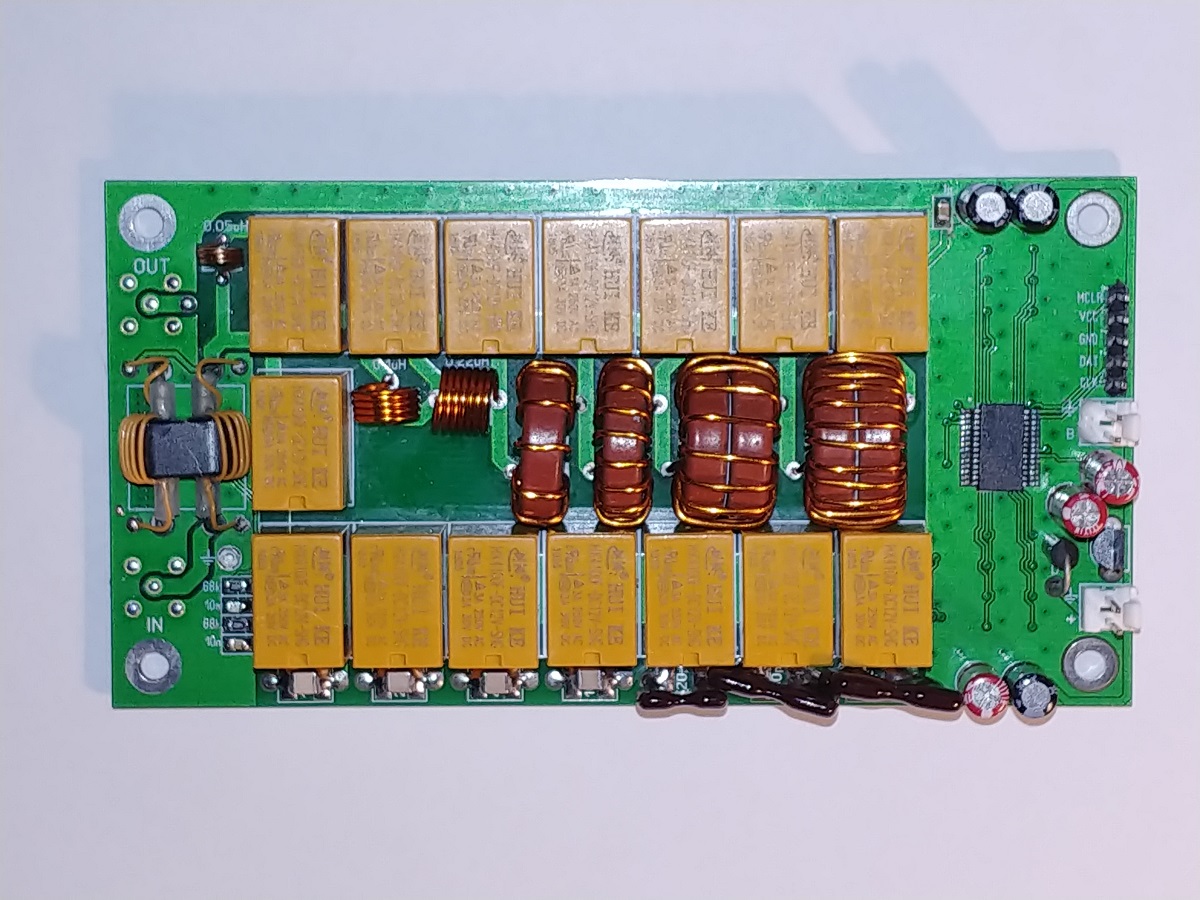
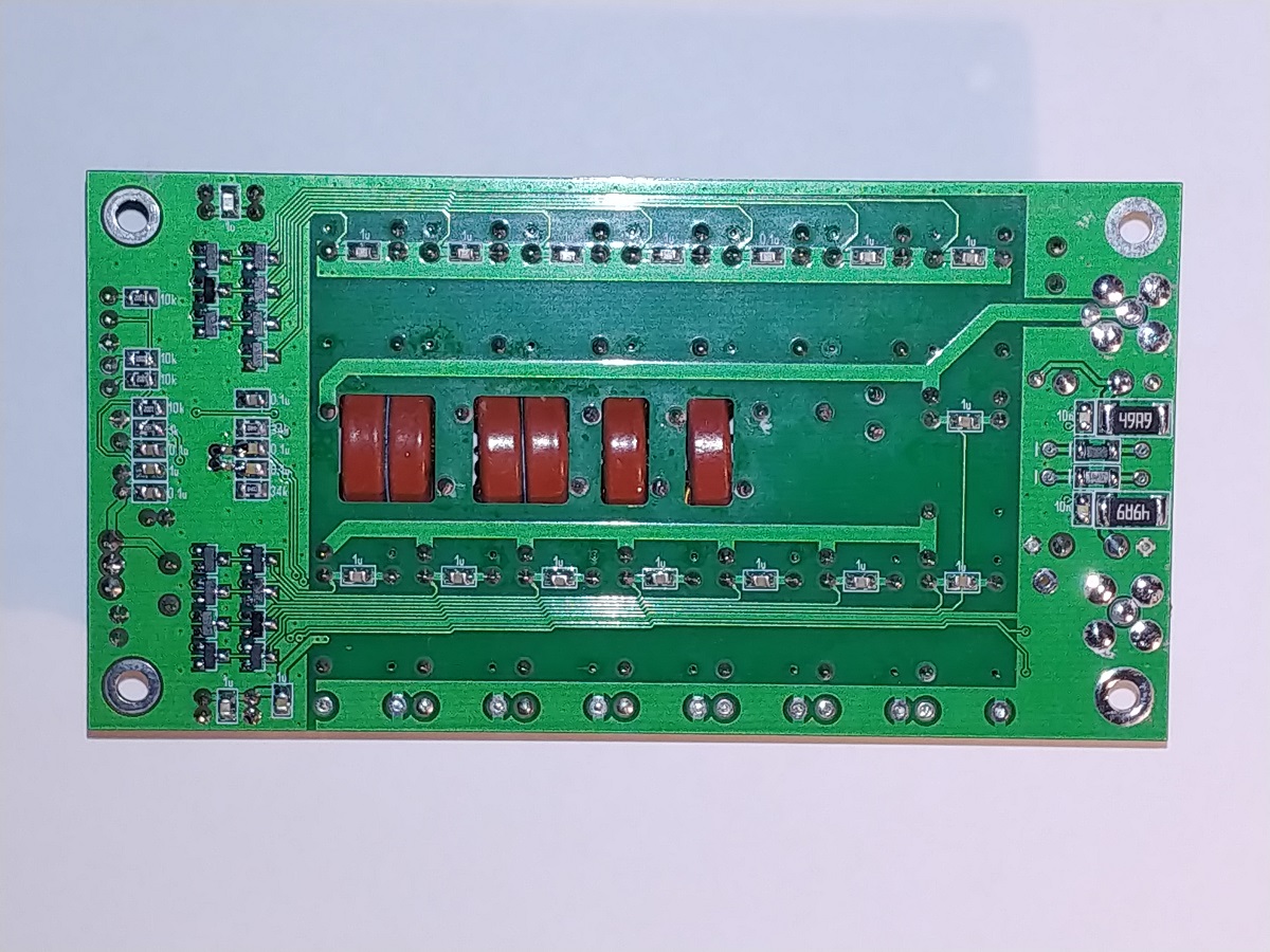
N7DDC ATU-100 extended board
The flexible tunable firmware for ATU from 5x5 to 7x7 elements, up to 1500 Watt measured power
The autor's 7x7 elements 100 Watt version
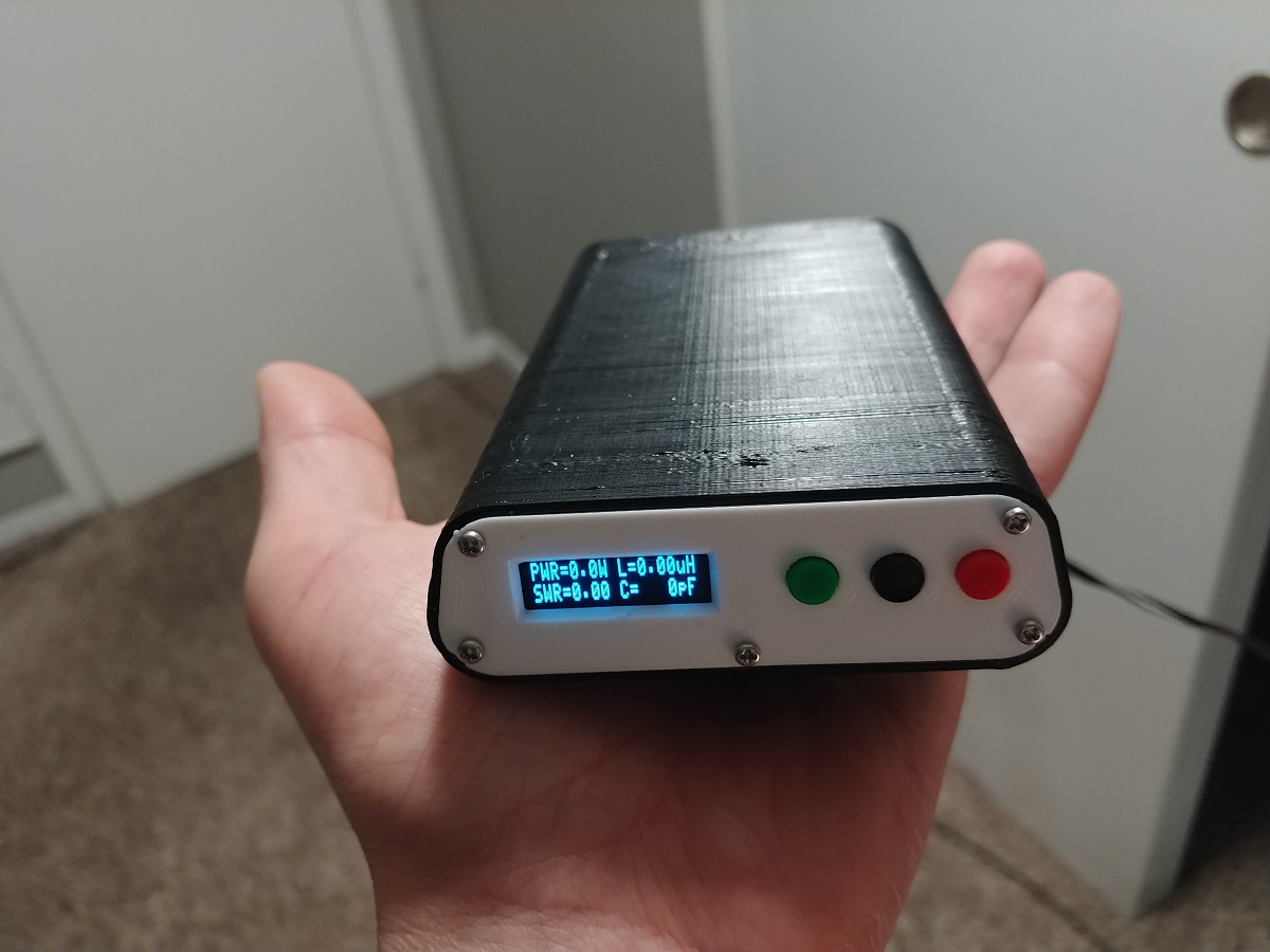
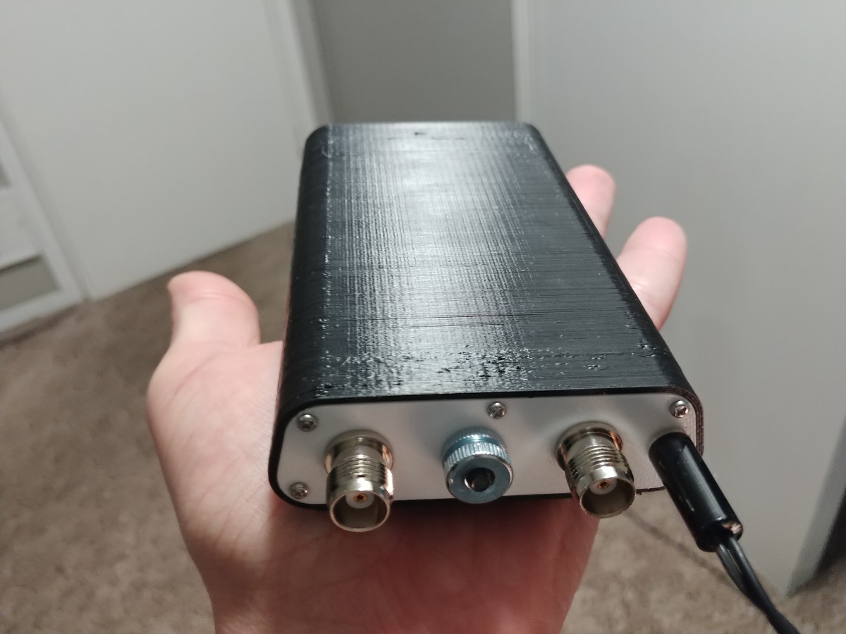
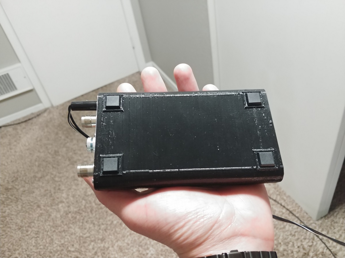
3D printed housing for 0.91" OLED display, 3 buttons and TNC RF connectors
AS example 1000 Watt ATU designed by EU2AV (VIDEO)
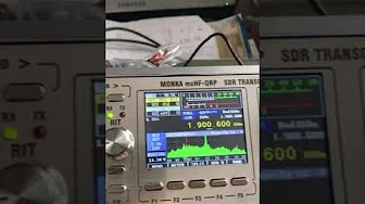
ATU-100 7x7 demo with M0NKA transceiver in Auto mode, LZ2GX (VIDEO)
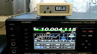
ATU-100 5x5 Auto mode with FTdx-1200 (VIDEO)
The first video from N7DDC, 5x5 elements, ENGLISH subtitles (VIDEO)